
Manual

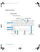
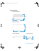
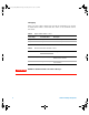
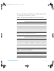
Table Of Contents
- Agilent U2121A-101 RF Switch Driver Board
- Safety Symbols
- Environmental Conditions
- Regulatory Markings
- Waste Electrical and Electronic Equipment (WEEE) Directive 2002/96/EC
- Contents
- Introduction
- Standard Purchase Items Checklist
- Product at a Glance
- Connector Pins Configuration
- Installation Guide
- Supported Switches
- Product Characteristics and Specifications
- Maintenance
- Disassemble Procedure
- Ordering Info
- Appendix A: Control Instructions
- Appendix B: Y1157A Cable Assembly Instructions

8 U2121A-101 Operating Guide
IO mapping
There are three main control bits used in the U2121A- 101 as shown
in tables below. These control bits also refers to the U2121A control
bit status.
Ta ble 4 Output enable/disable control
Control Stage Control Bit, DO14 Description
Output disabled OFF (0) To disable all outputs in U2121A
- 101
Output enabled ON (0) To enable all outputs in U2121A
- 101
Ta ble 5 Position information read back control
RF Switches Control Bit Description
D16 D15
8765x and 8762/3/4 OFF (0) ON (1) Read position information from 8765x and
8762/3/4 series switches
N181x ON (1) OFF (0) Read position information from N181x
series switches
WARNING
DO NOT set both D15 and D16 control bits to ON stage!
U2931A Operating Guide.book Page 8 Tuesday, June 10, 2008 10:17 AM