U2931A Operating Guide.
U2931A Operating Guide.book Page II Tuesday, June 10, 2008 10:17 AM Notices ® Agilent Technologies, Inc. , 2008 Warranty No part of this manual may be reproduced in any form or by any means (including electronic storage and retrieval or translation into a foreign language) without prior agreement and written consent from Agilent Technologies, Inc. as governed by United States and international copyright laws.
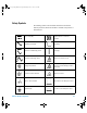
U2931A Operating Guide.book Page III Tuesday, June 10, 2008 10:17 AM Safety Symbols The following symbols on the instrument and in the documentation indicate precautions, which must be taken to maintain safe operation of the instrument.
U2931A Operating Guide.book Page IV Tuesday, June 10, 2008 10:17 AM General Safety Information WARN IN G CAU T ION • Do not load the output terminals above the specified current limits. • Do not use the device if it appears damaged or defective. • Observe all markings on the device before connecting any wiring to the device. • Do no operate the device in the presence of flammable gases or fumes. • Do no install substitute parts or perform any unauthorized modification to the device.
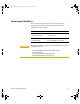
U2931A Operating Guide.book Page V Tuesday, June 10, 2008 10:17 AM Environmental Conditions This instrument is designed for indoor use and in an area with low condensation. The table below shows the general environmental requirements for this instrument.
U2931A Operating Guide.book Page VI Tuesday, June 10, 2008 10:17 AM Regulatory Markings The CE mark is a registered trademark of the European Community. This CE mark shows that the product complies with all the relevant European Legal Directives. ICES/NMB-001 indicates that this ISM device complies with the Canadian ICES-001. Cet appareil ISM est confomre a la norme NMB-001 du Canada. The C-tick mark is a registered trademark of the Spectrum Management Agency of Australia.
U2931A Operating Guide.book Page VII Tuesday, June 10, 2008 10:17 AM Waste Electrical and Electronic Equipment (WEEE) Directive 2002/96/EC This instrument complies with the WEEE Directive (2002/96/EC) marking requirement. This affixed product label indicates that you must not discard this electrical/electronic product in domestic household waste.
U2931A Operating Guide.book Page VIII Tuesday, June 10, 2008 10:17 AM DECLARATION OF CONFORMITY According to EN ISO/IEC 17050-1:2004 Generic example Manufacturer’s Name: Manufacturer’s Address: Agilent Technologies Microwave Products (M) Sdn.
U2931A Operating Guide.book Page IX Tuesday, June 10, 2008 10:17 AM Product Regulations EMC Performance Criteria IEC 61326-1:2002 / EN 61326-1:1997+A1:1998+A2:2001+A3:2003 CISPR 11:1990 / EN 55011:1990 – Group 1 Class A IEC 61000-4-2:1995 / EN 61000-4-2:1995 (ESD 4kV CD, 8kV AD) IEC 61000-4-3:1995 / EN 61000-4-3:1996 (3V/m, 80% AM) IEC 61000-4-4:1995 / EN 61000-4-4:1995 (EFT 0.5kV line-line, 1kV line-earth) IEC 61000-4-5:1995 / EN 61000-4-5:1995 (Surge 0.
U2931A Operating Guide.
U2931A Operating Guide.book Page 1 Tuesday, June 10, 2008 10:17 AM Contents Introduction 2 Standard Purchase Items Checklist 4 Product at a Glance 5 Product outlook 5 Product dimensions 6 Connector Pins Configuration 7 Installation Guide 10 A. Check your system 11 B. Install prerequisites and software 12 C. Connect the hardware solution to your PC 14 D.
U2931A Operating Guide.book Page 2 Tuesday, June 10, 2008 10:17 AM Introduction The Agilent U2121A- 101 (also known as U2931A) RF switch driver with cable is an adapter board designed for use with the Agilent U2121A digital IO device. It enables you to control various types of RF switches easily and has enhanced driving capability and consists of different types of connectors to suit different switches.
U2931A Operating Guide.book Page 3 Tuesday, June 10, 2008 10:17 AM Power supply The switches on this module are powered by the provided power adapter. There is only one power supply voltage available for this module, which is 24 VDC, 2.5 A. Power consumption The U2121A- 101 can drive up to 1500 mA continuously using the provided power supply. For each channel, it is able to drive up to 300 mA load per switch.
U2931A Operating Guide.book Page 4 Tuesday, June 10, 2008 10:17 AM Standard Purchase Items Checklist Verify that you have received the following items with your purchase. U2121A- 101 RF switch driver board with cable purchase. If anything is missing or damaged, please contact the nearest Agilent Sales Office.
U2931A Operating Guide.
U2931A Operating Guide.book Page 6 Tuesday, June 10, 2008 10:17 AM Product dimensions Top view (without casing) 72.00 mm 150.00 mm Top view (with casing) 85.00 mm 153.00 mm Front view (with casing) Side view (with casing) 38.00 mm 6 85.
U2931A Operating Guide.book Page 7 Tuesday, June 10, 2008 10:17 AM Connector Pins Configuration Pin out configuration for all terminals Table 1 Table 2 Table 3 U2121A-101 Operating Guide 8762/2/3 and 8765x-324 Series switches (X1 to X5) Pin Function 1 Position #1 2 Position #2 3 N.C. 4 +24 V 8765x-024 Series switches (SL1 to SL5) Pin Function 1 Position #2 2 N.C. 3 +24 V 4 +24 V 5 Position #1 N181X Series switches (SV1 to SV5) Pin Function Pin Function 1 GND 2 +5 V 3 N.
U2931A Operating Guide.book Page 8 Tuesday, June 10, 2008 10:17 AM IO mapping There are three main control bits used in the U2121A- 101 as shown in tables below. These control bits also refers to the U2121A control bit status.
U2931A Operating Guide.book Page 9 Tuesday, June 10, 2008 10:17 AM Each of the five RF switch channels uses two digital output pins and two digital input pins during the operation.
U2931A Operating Guide.book Page 10 Tuesday, June 10, 2008 10:17 AM Installation Guide Follow the step- by- step instructions shown in the following flowchart to get started with the preparations and installations of your Agilent U2121A- Based RF Switch Driver Software. N O TE You need to install the IVI-COM driver if you are going to use the U2121A- 101 with Agilent VEE Pro, LabVIEW, or Microsoft® Visual Studio®. A. Check your system B. Install prerequisites and software C.
U2931A Operating Guide.book Page 11 Tuesday, June 10, 2008 10:17 AM A. Check your system Prior to any installation or configuration, please ensure that your PC meets the following minimum system requirements. Hardware requirements Hardware required Specification (minimum) Processor 1.
U2931A Operating Guide.book Page 12 Tuesday, June 10, 2008 10:17 AM B. Install prerequisites and software There are two options you may choose from to install the prerequisites and Agilent U2121A- Based RF Switch Driver Software. You may choose to install from the provided Product Reference CD- ROM or obtain the installation software from Agilent's website to install the software.
U2931A Operating Guide.book Page 13 Tuesday, June 10, 2008 10:17 AM 4 If the installation menu does not appear after a few seconds, go to Start > Run and type :\Application\setup.exe where is your CD- ROM drive location. 5 Click OK to begin the installation of the following items. 6 If you do not have any of the prerequisites installed, the InstallShield Wizard software prerequisite will appear. 7 Click OK to begin the installation of the listed missing prerequisites.
U2931A Operating Guide.book Page 14 Tuesday, June 10, 2008 10:17 AM 3 Disconnect any instrument that is connected to your PC and close all other applications on your PC. 4 Double- click the saved installation file to begin installation. 5 If you do not have any of the prerequisites installed, the InstallShield Wizard software prerequisite will appear. 6 Click OK to begin the installation of the listed missing prerequisites.
U2931A Operating Guide.book Page 15 Tuesday, June 10, 2008 10:17 AM WARN IN G The total allowable current is 1500 mA. Please ensure that the total current consumption is not more than 1500 mA. [1] SL1 to SL5 refers to the 8762/3/4 and 8765x-324 RF switch connectors for Ch1 to Ch5. [2] X1 to X5 refers to the 8765x-024 RF switch connectors for Ch1 to Ch5. [3] SV1 to SV5 refers to the N181x RF switch connectors for Ch1 to Ch5. [4] X7 refers to the connector for general I/O on the switch driver board.
U2931A Operating Guide.book Page 16 Tuesday, June 10, 2008 10:17 AM 6 The Agilent Interactive IO dialog box will appear. Click Send & Read to send the *IDN? default command. The instrument’s response should appear in the Instrument Session History panel. 7 If the Connection Expert can successfully communicate with the U2121A, this indicates that the instrument has been installed correctly. N O TE • The IO Control will launch automatically when you start your PC.
U2931A Operating Guide.book Page 17 Tuesday, June 10, 2008 10:17 AM 8 Double- click Agilent U2121A-Based RF Switch Driver Software icon on your desktop or go to Start > All Programs > Agilent U2121A-Based RF Switch Driver > U2121A-Based RF Switch Driver Software to launch the software. 9 The U2121A- Based RF Switch Driver Software screen will appear. 10 To start the application, click on the Start button. The Select USB Device dialog box will appear displaying the connected U2121A devices.
U2931A Operating Guide.book Page 18 Tuesday, June 10, 2008 10:17 AM 12 Use the toggle paddle for each channel in the program to select respective switch position. 13 Use the checkbox and the Send Output button in the General Output section to control the output devices connected to the RF switches. 14 To view the General Input Status, click the Refresh Input Status Bits button in the General Input section. 15 Click Exit to leave the program, all switches will be disabled upon exiting the program.
U2931A Operating Guide.book Page 19 Tuesday, June 10, 2008 10:17 AM Supported Switches The U2121A- 101A supports three types of Agilent RF switches as shown in Table 9. User can choose to drive the same switches in all five channels or a mixture of three switches for five channels. However, only one type of switch can be used in a channel at a time. Do not use multiple types of switches in the same channel. Drive modes The RF switch driver board drives the switches using the open collector drive method.
U2931A Operating Guide.book Page 20 Tuesday, June 10, 2008 10:17 AM Pulse drive Pulse drive method controls the switches using a ~30 ms pulse. As shown in the figure below, the control signal is applied to one of the control bit and held for the preset time. Output enable Drive ChA Drive active Drive ChB Drive active General IO There are three digital outputs and three digital inputs available in the U2121A- 101 as an auxiliary port. These three output pins are capable to drive up to 300 mA of load.
U2931A Operating Guide.book Page 21 Tuesday, June 10, 2008 10:17 AM Product Characteristics and Specifications Table 8 General characteristics of the U2121A-101 RF switch driver board General Characteristics Power consumption • +24 VDC, 2.
U2931A Operating Guide.book Page 22 Tuesday, June 10, 2008 10:17 AM Table 9 Type of switches supported by U2121A-101 RF switch driver board Switch/Attenuator Reference Document No.
U2931A Operating Guide.book Page 23 Tuesday, June 10, 2008 10:17 AM Maintenance 1 Power off your device, unplug the DC power jack and remove the RF switch driver board interface cable from your device. 2 Remove your device from the plastic casing. 3 Shake out any dirt that may have accumulated on the RF switch driver board. 4 Wipe your RF switch driver board with a dry cloth and install the plastic casing back in place.
U2931A Operating Guide.book Page 24 Tuesday, June 10, 2008 10:17 AM Disassemble Procedure The following steps shows the disassemble procedure of the RF switch driver board from its casing. 1 Remove the two screws on either side of the board. 2 Remove the side panel from the casing.
U2931A Operating Guide.book Page 25 Tuesday, June 10, 2008 10:17 AM 3 Remove the PCA from the casing. 4 The disassembled RF switch driver board is shown below.
U2931A Operating Guide.book Page 26 Tuesday, June 10, 2008 10:17 AM Ordering Info To order the U2931A RF switch driver, please select the U2121A and U2121A–101 ordering options. This will include the U2121A digital IO device and U2121A–101 RF switch driver board and cable. You can also order the U2931A RF switch driver board as a standalone unit by choosing the U2931A–101 ordering option.
U2931A Operating Guide.book Page 29 Tuesday, June 10, 2008 10:17 AM Appendix A: Control Instructions The COM driver minimum system requirements are as shown below. Minimum System Requirements PC hardware 450 MHz Pentium II or higher, 128 MB RAM, 40 GB hard disk space, CD-ROM drive. Operating system Windows® XP Professional or Home Edition, Service Pack 1 or later, Windows® 2000 Professional, Service Pack 4 or later.
U2931A Operating Guide.book Page 30 Tuesday, June 10, 2008 10:17 AM To set digital output. 1 To enable digital output control, set Ch14 to ON (1). 2 For channel 1 to channel 5, only activated one bit at a time. Do not activate both bits together because this will damage your RF switches. 3 Some RF switches will need pulse current control instead of continuous current control. Please refer to the respective RF switches' datasheets for more information. The wrong control method will lead to RF switch damage.
U2931A Operating Guide.book Page 31 Tuesday, June 10, 2008 10:17 AM Appendix B: Y1157A Cable Assembly Instructions The Y1157A is a 10- pin ribbon connector to 9- pin D- Sub cable kit which contains materials to build four cables. The key to building the cables correctly is to understand the orientation of the socket pins on the distribution boards and the pin number orientation of the cable connectors. This orientation is shown in Figure B- 1.
U2931A Operating Guide.book Page 32 Tuesday, June 10, 2008 10:17 AM Strain relief Pin 1 of ribbon cable Align connector contacts over cable lines “Press” until metal contacts are no longer visible (same for D-Sub connector) Figure B-2 Y1157A connector orientation and ribbon cable routing 3 Move the connectors to the ends of the cable, allowing for some overlap on the D- Sub connector end and strain relief on the ribbon cable connector end. Note the orientation of the connectors and cable in Figure B- 2.
U2931A Operating Guide.book Page 33 Tuesday, June 10, 2008 10:17 AM www.agilent.