
User manual

G1369A LAN Interface User Manual 17
Getting Started 2
Installing and cabling the LAN Interface
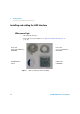
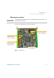
6 Carefully slide the LAN Interface into the slot. Some pressure may be
necessary to properly seat the board. Tighten the screws.
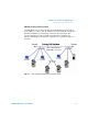
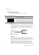
7 Disconnect your PC from the network and connect the PC network card to
the instrument's LAN Interface using a Crossover Network cable
(point-to-point) or alternatives, see page 10 and page 11.
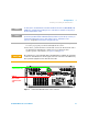
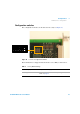
Figure 9 Connect the LAN cable to the correct connector
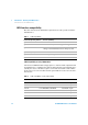
NOTE
In 1100 systems, the LAN Interface should be installed in the detector (DAD, MWD, FLD,
VWD) due to its higher data handling rate. If no 1100 detector available, use the pump or
the autosampler (in this order).
NOTE
The LAN Interface is shipped with the Bootp initialization mode and will use the
parameters (IP, Subnet Mask and Default Gateway addresses) from a Bootp server. If you
need another initialization mode or other settings, refer to “Initialization mode
selection” on page 20 for details before doing the next step.
CAUTION
Be careful that you connect the LAN cable to the LAN Interface and NOT one of the CAN
connections. The CAN bus uses 12-Volt signals, and a misconnection to the CAN bus may
destroy network equipment on the other end of the cable.
LAN
comunication only
CAN for
inter-module
communication
only