Agilent G1369A LAN Interface User Manual Agilent Technologies
Notices © Agilent Technologies, Inc. 2003 Warranty No part of this manual may be reproduced in any form or by any means (including electronic storage and retrieval or translation into a foreign language) without prior agreement and written consent from Agilent Technologies, Inc. as governed by United States and international copyright laws. The material contained in this document is provided “as is,” and is subject to being changed, without notice, in future editions.
In This Guide… This guide contains information to install the LAN Interface (G1369A). 1 Introduction - Around your LAN Interface In this chapter you will find an introduction to the LAN Interface and its function. 2 Getting Started In this chapter you will find instructions to help you to set-up your LAN Interface. 3 Getting Help In this chapter you will find support information about troubleshooting, repair and the Agilent web.
G1369A LAN Interface User Manual
Contents Introduction to the LAN Interface 8 LAN control - what exactly does it do? LAN Interface - what has to be done? LAN control configurations 10 LAN Interface compatibility 12 Installing and cabling the LAN Interface What you will get 14 What you have to do first 15 9 9 14 LAN Interface configuration 18 TCP/IP parameter configuration 18 18 Configuration switches 19 Initialization mode selection 20 Link configuration selection 23 Automatic configuration with Bootp 24 Configuring the CAG Bootp serve
Contents Reporting of Problems Agilent Web 45 Glossary 6 45 46 G1369A LAN Interface User Manual
Agilent G1369A LAN Interface User Manual 1 Introduction - Around your LAN Interface Introduction to the LAN Interface 8 LAN control - what exactly does it do? 9 LAN Interface - what has to be done? 9 LAN control configurations 10 Local configuration using cross-over cable 10 LAN using a HUB and twisted pair cables 10 LAN with existing customer network 11 LAN Interface compatibility 12 In this chapter you will find an introduction to the LAN Interface and its function.
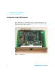
1 Introduction - Around your LAN Interface Introduction to the LAN Interface Introduction to the LAN Interface The LAN Interface (Local Area Network) is the Agilent replacement for the previously used HP JetDirect card in the Agilent 1100 series HPLC modules and the 8453 UV-vis spectrophometer.
Introduction - Around your LAN Interface Introduction to the LAN Interface 1 LAN control - what exactly does it do? In its simplest form… • control of your instrument and acquires data “remotely” from your desktop (easier access), • a direct replacement for GP-IB (HP-IB) interface protocol, • allows your instrument to be placed anywhere on the laboratory/corporate network, • improves lab “ergonomics” (better organization), LAN Interface - what has to be done? • install LAN Interface into the instrument •
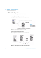
1 Introduction - Around your LAN Interface Introduction to the LAN Interface LAN control configurations The basic LAN configurations are shown below. Local configuration using cross-over cable The simplest way is a configuration with a single system. Patch-cable Cross-over Shielded 3 m (5023-0203) Figure 2 Local configuration using cross-over cable LAN using a HUB and twisted pair cables More complicated setup than direct cross-over connection.
Introduction - Around your LAN Interface Introduction to the LAN Interface 1 LAN with existing customer network Use MDI/MDI-X port or “Cascade” Port with standard twisted pair cable to connect Hub to a “parent” hub. IP Addresses and other TCP/IP configuration information MUST be provided by the customer’s IT organization. The customer LAN must be able to handle instrument data and must have sufficient bandwidth for instrument acquisition (no overnight backups over the LAN).
1 Introduction - Around your LAN Interface Introduction to the LAN Interface LAN Interface compatibility The table below lists the minimum requirements for LAN operation with the LAN Interface. Table 1 LAN Compatibility Instrument/Operating Software Revision (minimum) Agilent 1100 modules Firmware A.03.80 and Revision 2 mainboard, see Table 2 Agilent Control Module G1323A All revsions show just the status page, no editing possible Agilent Control Module G1323B All revsions below B.02.
Agilent G1369A LAN Interface User Manual 2 Getting Started Installing and cabling the LAN Interface 14 What you will get 14 What you have to do first 15 LAN Interface configuration 18 TCP/IP parameter configuration 18 Configuration switches 19 Configuration switches 19 Initialization mode selection 20 Using Stored 21 Using Default 22 Bootp 20 Bootp & Store 20 Link configuration selection 23 Automatic configuration with Bootp 24 Configuring the CAG Bootp server program 24 Storing the settings permanently wi
2 Getting Started Installing and cabling the LAN Interface Installing and cabling the LAN Interface What you will get • G1369A LAN Interface • LAN cables (for part numbers see “Repair and Parts Information” on page 44) Patch-cable Twisted pair Shielded 7 m (5023-0202) Patch-cable Cross-over Shielded 3 m (5023-0203) CD-ROM with the manual LAN Interface (1369-60001) Figure 5 14 What you will get (Content of G1369A) G1369A LAN Interface User Manual
Getting Started Installing and cabling the LAN Interface 2 What you have to do first NOTE Use an ESD (Electro-Static Discharge) wrist strap when handling electronics. Refer to your instrument manual for details. 1 Remove the LAN Interface from it’s packaging.
2 Getting Started Installing and cabling the LAN Interface 2 Note the MAC (Media Access Control) address for further reference. The MAC or hardware address of the LAN Interface is a world wide unique identifier. No other network device will have the same hardware address. The MAC address can be found on a label on the card (see Figure 6 on page 15).
Getting Started Installing and cabling the LAN Interface 2 NOTE In 1100 systems, the LAN Interface should be installed in the detector (DAD, MWD, FLD, VWD) due to its higher data handling rate. If no 1100 detector available, use the pump or the autosampler (in this order). NOTE The LAN Interface is shipped with the Bootp initialization mode and will use the parameters (IP, Subnet Mask and Default Gateway addresses) from a Bootp server.
2 Getting Started LAN Interface configuration LAN Interface configuration TCP/IP parameter configuration To operate properly in a network environment, the LAN Interface must be configured with valid TCP/IP network parameters.
Getting Started LAN Interface configuration 2 Configuration switches The configuration switches are mounted on the card, see Figure 10. ON 1 2 3 4 5 6 7 8 Figure 10 Location of Configuration Switches The LAN Interface is shipped with all switches set to OFF, as shown above.
2 Getting Started LAN Interface configuration Initialization mode selection The following initialization (init) modes are selectable: Table 4 Initialization Mode Switches SW 4 SW 5 SW 6 Init Mode OFF OFF OFF Bootp OFF OFF ON Bootp & Store OFF ON OFF Using Stored OFF ON ON Using Default ON 1 2 3 4 5 6 7 8 Bootp When the initialization mode “Bootp” is selected, the card tries to download the parameters from a Bootp Server.
Getting Started LAN Interface configuration 2 waits for the Bootp cycle to be completed, closes the Bootp Server and powers off the card. Then he selects the initialization mode “Using Stored” and powers on the card again. From now on, he is able to establish the TCP/IP connection to the card with the parameters obtained in that single Bootp cycle.
2 Getting Started LAN Interface configuration Using Default When “Using Default” is selected, the factory default parameters are taken instead. These parameters enable a TCP/IP connection to the LAN Interface without further configuration, see Table 5. Active Parameter Default Parameter Figure 14 NOTE Using Default (Principle) Using the default address in your local area network may result in network problems. Take care and change it to a valid address immediately.
Getting Started LAN Interface configuration 2 Link configuration selection The LAN Interface supports 10 or 100 Mbps operation in full- or half-duplex modes. In most cases, full-duplex is supported when the connecting network device - such as a network switch or hub - supports IEEE 802.3u auto-negotiation specifications. When connecting to network devices that do not support auto-negotiation, the LAN Interface will configure itself for 10- or 100-Mbps half-duplex operation.
2 Getting Started Automatic configuration with Bootp Automatic configuration with Bootp When automatic configuration with Bootp is selected and the LAN Interface is powered on, it broadcasts a BOOTP (Bootstrap Protocol) request that contains its MAC (hardware) address. A BOOTP server daemon searches its database for a matching MAC address, and if successful, sends the corresponding configuration parameters to the card as a BOOTP reply.
Getting Started Automatic configuration with Bootp 2 The MAC or hardware address of the LAN Interface is a world wide unique identifier. No other network device will have the same hardware address. The MAC address can be found on a label on the card, see Figure 6 on page 15. Figure 15 Bootp Server 4 Identify your LAN Interface by the MAC address, see Figure 15.
2 Getting Started Automatic configuration with Bootp 6 Specify the Host Name (LC1100-01), the IP address (134.40.24.230), the Comment (LC1100-01) and the Subnet Mask 255.255.248.0 and the Gateway (134.40.24.1). NOTE If you are working in a network system, you need your own addresses. Contact your local IT group. Figure 17 Add Bootp Entry - Enter your parameter 7 Exit with OK. 8 Select Configure -> Bootp Manager. All entries made above are shown in Figure 18 on page 27.
Getting Started Automatic configuration with Bootp Figure 18 2 Bootp Manager 9 Press Apply to activate the changes. 10 Press OK to exit the Bootp Manager and power cycle the instrument with the LAN Interface, to force it to send a new bootp request again. This time, the MAC address will be recognized by the Bootp Server (Figure 19). It will send the configured IP address and subnet mask information which are necessary for communication to the LAN Interface. IP address LAN Interface is 134.40.24.
2 Getting Started Automatic configuration with Bootp NOTE When using this Bootp mode, the parameters are not written into the non-volatile memory of the card. If you delete this Bootp Configuration, the LAN Interface will show up as shown in Figure 15 on page 25 (Bootp mode). If you want to store your parameters permanently on the card (for use without the CAG Bootp server), refer to “Storing the settings permanently with Bootp program” on page 29.
Getting Started Storing the settings permanently with Bootp program 2 Storing the settings permanently with Bootp program If you want to change parameters of the card using the Bootp follow the instructions below. NOTE Use an ESD (Electro-Static Discharge) wrist strap when handling electronics. Refer to your instrument manual for details. 1 Turn off the module that hosts the LAN Interface and remove the card.
2 Getting Started Manual configuration Manual configuration Manual configuration only alters the set of parameters stored in the non-volatile memory of the card. It never affects the currently active parameters. Therefore, manual configuration can be done at any time. A power cycle is mandatory to make the stored parameters become the active parameters, given that the initialization mode selection switches are allowing it.
Getting Started Manual configuration 2 With Telnet Whenever a TCP/IP connection to the card is possible (TCP/IP parameters set by any method), the parameters may be altered by opening a Telnet session. 1 Open the system (DOS) prompt window by clicking on Windows START button and select “Run...”. Type “cmd” and press OK.
2 Getting Started Manual configuration Table 7 NOTE Telnet Commands Value Description ? displays syntax and descriptions of commands / displays current settings ip sets new ip address sn set new subnet mask gw
Getting Started Manual configuration 2 5 Change the IP address (in this example 134.40.24.158) and type “/” to list current settings. change of TCP/IP setting Initialization mode is Bootp The connected PC/Bootserver is 134.40.24.
2 Getting Started Manual configuration With Handheld Controller To configure the TCP/IP parameters before connecting the card to the network, the Handheld Controller (G1323B with firmware B.02.02 or above for 1100 series modules only, see LAN Interface compatibility 12.) can be used. 1 Press F5 “Views”, select “System” and press the “Enter” key. 2 Press F2 “Configure”, select the module where the LAN Interface is installed and press the “Enter” key (Figure 25).
Getting Started Manual configuration 2 4 A Warning message shall pop up. Press “Continue” (Figure 27). Figure 27 Warning message 5 After the Handheld Controller was reading out the LAN Interface you will get an overview of all the parameters that are set in the card (LAN Interface Status Page). The information corresponds to the information in Figure 23 on page 32. Figure 28 LAN Interface Status Page In Figure 29 on page 36 the complete listing is shown.
2 Getting Started Manual configuration Agilent Technologies G1369A FW Revision : A.01.01 MAC Address : 0030d3060122 -------------------------------Init Mode : Bootp Bootp Server : 134.40.30.184 -------------------------------TCP/IP Properties - active IP Address : 134.40.24.230 Subnet Mask : 255.255.248.0 Def. Gateway : 134.40.24.1 - stored IP Address : 134.40.24.160 Subnet Mask : 255.255.248.0 Def. Gateway : 134.40.24.
Getting Started Manual configuration Figure 31 2 TCP/IP parameters 7 Move to the parameter you want to change, enter the new value and press “Enter”.
2 Getting Started Manual configuration 8 If you completed your changes, press “Done” to leave the Service section. 9 Press F6 “Done” and restart the module by pressing “OK” .
Getting Started PC and Agilent ChemStation setup 2 PC and Agilent ChemStation setup PC Setup for Local Configuration This procedure describes the change of the TCP/IP settings on your PC to match the LAN Interface default parameters in a local configuration (see also “Local configuration using cross-over cable” on page 10 and “Using Default” on page 22).
2 Getting Started PC and Agilent ChemStation setup Agilent ChemStation setup 1 Start the Configuration Editor of the Agilent ChemStation. Figure 35 Changing the TCP/IP settings of the Agilent ChemStation 2 Add a TCP/IP connection to communicate with the LAN Interface. Use the IP address of the LAN Interface. NOTE If using a corporate LAN, IP addresses need to be supplied by the responsible IT department. Also the LAN needs to be able to handle additional traffic.
Agilent G1369A LAN Interface User Manual 3 Getting Help Troubleshooting 42 Link Status LEDs 42 Error Messages 43 Repair and Parts Information 44 Agilent Support Information 45 Firmware Update 45 Reporting of Problems 45 Agilent Web 45 Glossary 46 In this chapter you will find support information about troubleshooting, repair and the Agilent web.
3 Getting Help Troubleshooting Troubleshooting If the LAN Interface does not successfully connect to the network, there are several ways to get status information from the card. Link Status LEDs On the card, near the RJ-45 connector, two status LEDs are mounted. See Figure 36. Activity Speed Figure 36 Status LEDs The LED named “Speed” shows the actual link speed.
Getting Help Troubleshooting 3 Error Messages The error messages are shown in the LAN Interface Status Page on the Control Module (G1323A/B) only, refer to “With Handheld Controller” on page 34. Agilent Technologies G1369A FW Revision : A.01.01 MAC Address : 0030d3060122 -------------------------------Init Mode : Bootp -------------------------------TCP/IP Properties - active IP Address : 0.0.0.0 Subnet Mask : not specified Def. Gateway : not specified - stored IP Address : 134.40.24.
3 Getting Help Repair and Parts Information Repair and Parts Information The repair level of the product Agilent G1369A LAN Interface is replacement of the complete board.
Getting Help Agilent Support Information 3 Agilent Support Information Firmware Update The LAN Interface’s firmware can be updated, using the firmware provided by the Agilent support web side, see “Agilent Web”. A procedure will be provided with the firmware.
3 Getting Help Glossary Glossary Table 12 46 Glossary Term / Acronym Definition 10/100Base-TX Twisted pair Ethernet cable. Bootp Bootstrap Protocol, an Internet protocol that enables a diskless workstation to discover its own IP address CAN Controller Area Network; a shared broadcast bus, which runs at speeds up to 1Mbit/sec; it is a serial data communications bus for real-time applications. CAG Chemical Analysis Group (Agilent term) DOS Disk Operating System.
Getting Help Glossary Table 12 3 Glossary Term / Acronym Definition LED Light Emitting Diode MAC address Media Access Control address, a hardware address that uniquely identifies each node of a network. MIO Modular Input/Output; interface specification from Hewlett-Packard RJ-45 connector Registered Jack-45, an eight-wire connector used commonly to connect computers onto a local-area networks (LAN), especially Ethernets.
3 48 Getting Help Glossary G1369A LAN Interface User Manual
www.agilent.com In This Book This guide contains information to install the LAN Interface (G1369A).
www.agilent.
www.agilent.