
Wireless Network User's Guide


Connection Panels and LED Indicators B
Agilent E6474A User’s Guide 139
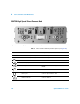
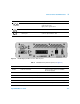
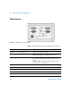
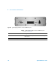
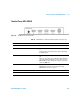
Trimble Placer GPS 455DR
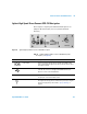
Ta ble 1 3 Trimble Placer connector panel descriptions (see Figure 65)
Figure 65 Trimble Placer connector panel
Connector Name Cable Part Number Opposite End of Cable Connects To
GPS Antenna E6450-80002 GPS antenna
Radio 8120-8650 GPS RS-232 port of the E645xx receiver
or
Serial port of the computer (this option requires a Dual Serial
Port PCMCIA card)
MDT/RTCM If you have a Differential GPS, connect its data cable to this
port.
This port is also used for sensor calibration. When calibrating,
remove the cable from the Radio port, then connect it to the
MDT/RTCM port. When calibration is complete, reconnect the
cable to the Radio port.
Heading Sensor Trimble p/n 30513 Heading Sensor lead: Connect to the heading sensor
ODO 0 Red lead: Connect to the odometer pulse signal
ODO 0 Black lead: Connect to ground.
Digital I/O (none) (not used)
Power 5182-1290 4-to-1 lighter socket adapter