
User`s guide


Performance Test Instructions Performance Tests
Agilent 81560A, 81561A, 81566A, & 81567A Optical Attenuator Modules, First Edition 53
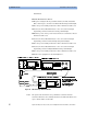
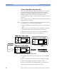
Measure the optical power after the Attenuator Module.
26 Open the shutter of the attenuator.
27 Set the l/4 and l/2 Retarder Plates for Linear Horizontal polarized
light.
28 Note the power reading as DUT Power P1 in the Test Record.
29 Set the l/4 and l/2 Retarder Plates to the corrected wavelength
dependent positions for Linear Vertical polarized light.
30 Note the power that is displayed on the power meter as DUT Power
P2 in the Test Record.
31 Set the l/4 and l/2 Retarder Plates to the corrected wavelength
dependent positions for Linear Diagonal polarized light.
32 Note the power reading as DUT Power P3 in the Test Record.
33 Set the l/4 and l/2 Retarder Plates to the corrected wavelength
dependent positions for Right Hand Circular polarized light.
34 Note the power reading as DUT Power P4 in the Test Record.
35 Calculate the Mueller coefficients, the Minimum and Maximum
transmission and finally the Polarization dependent Loss (PDL) as
described in the Test Record.
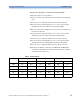
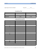
Table 4 Retarder Settings
λ/nm Linear Vertical Linear Diagonal Right Hand Circular
λ/4 Plate λ/2-Plate λ/4-Plate λ/2-Plate λ/4-Plate λ/2-Plate
1580 2.5° 46.2° 1.7° 23.3° 42.9° -17.1°
1560 1.2° 45.6° 0.8° 22.9° 44.0° -16.5°
1540 0° 45.0° 0° 22.5° 45.0° -15.1°
1520 -1.4° 44.3° -1.0° 22.0° 46.2° -13.8°
1500 -2.7° 43.6° -2.0° 21.4° 47.4° -12.4°