
User`s guide


Performance Test Instructions Performance Tests
Agilent 81560A, 81561A, 81566A, & 81567A Optical Attenuator Modules, First Edition 47
6 Set [P
SET
] to 0 dBm and wait for stabilizing. Note the reading of
[P
ACT
] in the Test Record.
7 Set [P
SET
] to any other value and wait until settling.
8 Change [P
SET
] back to the previous value and note the deviation of
[P
ACT
] in the Test Record.
9 Repeat the steps 6 to 8 for [P
SET
] = - 25 dBm and [P
SET
] = - 50 dBm.
Return Loss Test
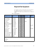
Carry out the following Return Loss Test at 1550 nm with single mode
fibers using the equipment listed in Table 3, “Equipment Required,” on
page 41. To adapt for the straight or angled contact versions of the
attenuator use the patchcords with appropriate connectors and the
adequate connector interfaces.
1 Turn the instruments on and allow the devices to warm up
(20..30min).
2 Make sure that all your connectors are clean and undamaged.
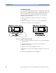
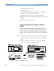
3 Connect the equipment as shown below in Figure 12.
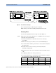
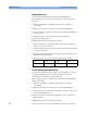
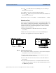
Figure 12 Return Loss Reference Setup
4 Set the attenuator and the power meter to the actual wavelength of
internal laser source of the return loss meter.
5 Disable the internal laser source, cover the end of the reference
cable and zero the return loss meter.
6 Uncover and clean the end of the reference cable and enable the
laser source.
7 Set the reflection reference R to 14.7 dB, the default value for the
return loss of the reference reflector cable 81610CC, and then select
the [REF CAL] parameter.
8163A 8163A