
User`s guide


Specifications Definition of Terms
36 Agilent 81560A, 81561A, 81566A, & 81567A Optical Attenuator Modules, First Edition
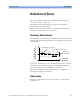
Measurement: With optical oscilloscope or transcient recorder.
NOTE Settling time excludes the time needed for the interpretation of the
command and for the internal communication between the mainframe
and the attenuator module.
Shutter Isolation
Ratio between transmitted powers with open and with closed shutter,
at an attenuator setting of 0 dB, expressed in dB.
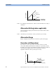
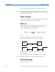
Tot al Los s
Change of power level after inserting the attenuator between two
connectorized patchcords, at an arbitrary attenuation setting,
expressed in dB. It can be calculated from:
where:
Pa=power measured at the end of the two patchcords.
Pb=power measured after the insertion of the attenuator.
Conditions: Jumper cables with reference connectors on both
attenuator ports.
Measurement: With laser source or LED and optical power meter.
NOTE Total loss includes the loss from one additional connection.
Wavelength Range
Usable wavelength range.
[] [][]
dBmdBmlog10dB
TL
ba
b
a
PP
P
P
A
−==
Laser
source
Power
meter
Laser
source
Power
meter
Attenuator
P
a
P
b