
User`s guide
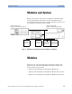

Getting Started with Attenuator Modules Optical Output
22 Agilent 81560A, 81561A, 81566A, & 81567A Optical Attenuator Modules, First Edition
Optical Output
Angled and Straight Contact Connectors
Angled contact connectors are available for Agilent Variable Optical
Attenuator modules and Agilent Variable Optical Attenuator modules
with Power Control. The inclusion of an angled contact connector is
not optionable, and depends on the module part number.
Angled contact connectors help you to control return loss, since
reflected light tends to reflect into the cladding, reducing the amount
of light that reflects back to the source.
CAUTION If the contact connector on your instrument is angled, you can only
use cables with angled connectors with the instrument.
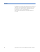
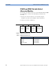
Figure 6 Angled and Straight Contact Connector Symbols
Figure 6 shows the symbols that tell you whether the contact
connector of your attenuator module is angled or straight. The angled
contact connector symbol is colored green.
You should connect straight contact fiber end connectors with neutral
sleeves to straight contact connectors and connect angled contact fiber
end connectors with green sleeves to angled contact connectors.
NOTE You cannot connect angled non-contact fiber end connectors with
orange sleeves directly to the instrument.
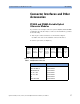
See “Accessories” on page 23 for further details on connector
interfaces and accessories.
Straight Contact
Connector Symbol
Angled Contact
Connector Symbol