
User`s guide


Getting Started with Attenuator Modules What is an Attenuator?
20 Agilent 81560A, 81561A, 81566A, & 81567A Optical Attenuator Modules, First Edition
Typical Use Models
Brief description Agilent's 8156xA Variable Optical Attenuators are instruments that
attenuate and control the optical power level of light in single mode
optical fibers. As plug-in modules for Agilent's Lightwave Multichannel
platform (8163A/B, 8164A/B, 8166A/B) they allow you to set the
attenuation factor and/or power level manually, or remotely via a
common computer interface. Their high accuracy combined with their
flexibility make them ideal as test and measurement equipment for the
modern telecommunication industry.
Modular Design for Multichannel
Platform
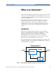
Agilent's 8156xA variable optical attenuators are a family of plug-in
modules for Agilent's Lightwave Multichannel Platform 8163A/B,
8164A/B and 8166A/B. The attenuator modules 81560A and 81561A
occupy one slot, while modules 81566A and 81567A occupy two slots.
The Agilent 8166A/B Lightwave Multichannel System with its 17 slots
can host up to 17 single slot modules (such as the 81560A and 81561A
attenuators) or up to 8 dual slot modules, (such as the 81566A and
81567A attenuators).
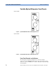
Variable Optical Attenuators Agilent's 81560A and 81561A are small and cost effective attenuator
modules with high resolution and low insertion loss. Various
calibration features allow you to set a reference power so that both the
attenuation and the power level, relative to the reference power, can
be set and displayed in the user interface. An integrated shutter can be
used for protection purposes or to simulate channel drops.
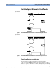
Attenuators with Power Control Agilent's 81566A and 81567A attenuators feature power control
functionality that allows you to set the output power level of the
attenuator. The attenuator module firmware uses the feedback signal
from a photo diode after a monitor coupler, both integrated in the
module, to set the desired power level at the output of the module.
When the power control mode is enabled, the module automatically
corrects power changes at the input to maintain the output level set by
the user. After an initial calibration for the uncertainties at connector
interfaces, absolute power levels can be set with high accuracy. The
absolute accuracy of these power levels depends on the accuracy of
the reference powermeter used for calibration.
Calibration Processes Comprehensive offset functionality in the firmware enhances the
calibration of the optical path in various test set-ups. There is an offset
for the attenuation factor, and an independent offset for the output
power level, to calibrate for losses due to the patch cords and
connectors. Additionally, wavelength and offset value pairs can be
stored in a table to compensate for wavelength dependent effects in
the optical path of the set-up. This allows you to set the optical power
level at your Device Under Test.