
User`s guide


List of Figures
Agilent 81560A, 81561A, 81566A, & 81567A Optical Attenuator Modules, First Edition 13
List of Figures
Figure 1 Agilent 81566A/81567A Optical Attenuators with Power Control . . . . 17
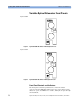
Figure 2 Agilent 81560A Attenuator with Straight Connector . . . . . . . 18
Figure 3 Agilent 81561A Attenuator with Angled Connector . . . . . . . 18
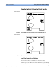
Figure 4 Agilent 81566A Attenuator with Power Control and Straight Connector . . 19
Figure 5 Agilent 81567A Attentuator with Power Control and Angled Connector . . 19
Figure 6 Angled and Straight Contact Connector Symbols . . . . . . . . 22
Figure 7 Mainframes, Variable Optical Attenuator Modules, and Options . . . . 25
Figure 8 Straight Contact Connectors . . . . . . . . . . . . . 27
Figure 9 Angled Contact Connectors . . . . . . . . . . . . . 28
Figure 10 Insertion Loss Reference Setup . . . . . . . . . . . . 44
Figure 11 Insertion Loss Test Setup . . . . . . . . . . . . . 45
Figure 12 Return Loss Reference Setup . . . . . . . . . . . . 47
Figure 13 Return Loss Test Setup . . . . . . . . . . . . . . 48
Figure 14 PDL Test Setup - Scanning Method . . . . . . . . . . . 49
Figure 15 PDL Reference Setup . . . . . . . . . . . . . . 50
Figure 16 PDL Test Setup - Mueller Method . . . . . . . . . . . 52
Figure 17 Relative Power Meter Uncertainty Setup . . . . . . . . . . 54