
User`s guide


Optional Performance Tests Performance Tests
Agilent 81600B Tunable Laser Source Family, Fourth Edition 139
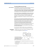
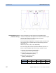
In order to keep the measurement time to a minimum, it is not necessary to
scan the whole of the wavelength ranges specified at step 6, but only
windows of ±25 pm (or approx. 25 points) centered around each
transmission peak, as shown in Figure 43 on page 140. The value is
indicative as it may depend on the exact free spectral range of the Fabry-
Perot etalon (which is also a function of the wavelength).
A preliminary measurement (not described here) of the Fabry-Perot etalon
is necessary in order to determine the positions of such windows.
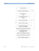
8 Set the TLS and PWM to the power settings specified at step 6 “Power
and Sweep settings for dynamic accuracy tests”
9 Set the Power-Meter wavelength to 1500 nm
(hp816x_set_PWM_wavelength);
10 Set the Power-Meter averaging time to 5 ms or higher
(hp816x_set_PWM_averaging_time);
11 Set the TLS to the current wavelength (hp816x_set_TLS_wavelength);
12 Take the corresponding power-measurement
(hp816x_set_PWM_readValue)
13 Update the current wavelength (add one wavelength step, see step 6
“Power and Sweep settings for dynamic accuracy tests”) and move to
the next wavelength window if necessary; return to step 10 and
proceed when finished.
14 Compute the following results from each reference scan (that is:
wavelength range):
P
th
dBm (j)
= 10*log10(max(Pmeas mW(
λ
))) – 2 ( j =1, 2, ... 30) [dBm]
representing the threshold level (2 dB below the maximum transmitted
power at each peak).
Select the 30 central transmission peaks, with positions
λ
peak
(j) ( j =1, 2, ... 30)
Find the corresponding 60 crossings of the thresholds
Pth dBm (j)
(via linear interpolation of the two closest measurements):
λ
ref
(i) ( j =1, 2, ... 60)
Do not disturb the test setup. After beginning the first of the following
measurements it is extremely important not to disturb the experimental
setup, in particular the connections and the fiber from the TLS to the
etalon.
NOTE