Agilent 81600B Tunable Laser Source Family User’s Guide Agilent Technologies
Notices © Agilent Technologies, Inc. 2002 - 2005 Warranty No part of this manual may be reproduced in any form or by any means (including electronic storage and retrieval or translation into a foreign language) without prior agreement and written consent from Agilent Technologies, Inc. as governed by United States and international copyright laws. Agilent Technologies, Deutschland GmbH Herrenberger Straße 130 71034 Böblingen, Germany.
Agilent Technologies Sales and Service Offices For more information about Agilent Technologies test and measurement products, applications, services, and for a current sales office listing, viesit our web site: http://www.agilent.com/comms/lightwave You can also contact one of the following centers and ask for a test and measurement sales representative.
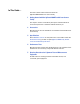
In This Guide.... This User’s Guide contains information about the Agilent 81600B Tunable Laser Source Family. 1 Getting Started with the Agilent 81600B Tunable Laser Source Family This chapter contains an introductory description of the Tunable Laser Source Family and aims to make the modules familair to you. 2 Accessories Describes the accessories available for each member of the Tunable Laser Source Family.
Table of Contents Getting Started with the Agilent 81600B Tunable Laser Source Family 11 General Safety Considerations 12 Safety Symbols Initial Inspection Line Power Requirements Operating Environment Input/Output Signals Storage and Shipment 12 Initial Safety Information for Agilent 81600B family modules Laser Safety Labels What is a Tunable Laser? Installation Front Panels Front Panel Controls and Indicators Typical Use Models Optical Output Polarization Maintaining Fiber Angled and Straight Contact
Specifications 33 Definition of Terms 35 General Definitions Absolute wavelength accuracy (continuous sweep mode) Absolute wavelength accuracy (stepped mode) Attenuation Dynamic power reproducibility (continuous sweep mode) Dynamic relative power flatness (continuous sweep mode) Effective linewidth External analog modulation - modulation depth External digital modulation - delay time Internal digital modulation - duty cycle Linewidth Maximum output power Mode-hop free tunability Operating temperature an
Supplementary Performance Characteristics General Performance Tests 68 69 71 Required Test Equipment Test Record Test Failure Instrument Specification Performance Test Instructions General test Setup Wavelength Meter Settings for all Wavelength Tests Wavelength Accuracy Absolute and Relative Wavelength Accuracy Mode-Hop Free Tuning Wavelength Repeatability Power Tests Maximum Output Power Power Linearity Power Flatness versus Wavelength Power Stability Signal-to-Source Spontaneous Emission Ratio Signa
Cleaning Procedures for Lightwave Test and Measurement Equipment 243 Safety Precautions Why is it important to clean optical devices ? What materials do I need for proper cleaning? Standard Cleaning Equipment Additional Cleaning Equipment Preserving Connectors General Cleaning Procedure How to clean connectors How to clean optical head adapters How to clean connector interfaces How to clean bare fiber adapters How to clean lenses and instruments with an optical glass plate How to clean instruments with a f
List of Figures Figure 1 Figure 2 Figure 3 Figure 4 Figure 5 Figure 6 Figure 7 Figure 8 Figure 9 Figure 10 Figure 11 Figure 12 Figure 13 Figure 14 Figure 15 Figure 16 Figure 17 Figure 18 Figure 19 Figure 20 Figure 21 Figure 22 Figure 23 Figure 24 Figure 25 Figure 26 Figure 27 Figure 28 Figure 29 Figure 30 Figure 31 Figure 32 Figure 33 Figure 34 Figure 35 Figure 36 Figure 37 Figure 38 Agilent 81600B Tunable Laser Source Family, Fourth Edition Agilent 81600B Tunable Laser Source Family modules (dual output,
Figure 39 Figure 40 Figure 41 Figure 42 Figure 43 Figure 44 10 Test Setup for Total Source Spontaneous Emission Test - Low SSE output . . . . . . . . . . . . . . . . . . . . . . . . . . . . . . . . . . . . . . . . . . Test Setup for Total Source Spontaneous Emission Test - High Power output . . . . . . . . . . . . . . . . . . . . . . . . . . . . . . . . . . . . . . . Test Flow - Dynamic Wavelength Accuracy Measurements . . . . . Setup for wavelength uncertainty verification in swept mode . . .
1 Getting Started with the Agilent 81600B Tunable Laser Source Family This chapter describes the Agilent 81600B Tunable Laser Source Family. General Safety Considerations. . . . . . . . . . . . . . . . . . . . . . . 12 Initial Inspection . . . . . . . . . . . . . . . . . . . . . . . . . . . . . . . . . . . . . . . 13 Safety Symbols . . . . . . . . . . . . . . . . . . . . . . . . . . . . . . . . . . . . . . . . 12 Line Power Requirements . . . . . . . . . . . . . . . . . . . . . . . . . . . . . . .
Getting Started with the Agilent 81600B Tunable Laser Source Family General Safety Considerations General Safety Considerations The following general safety precautions must be observed during all phases of operation, service, and repair of this instrument. Failure to comply with these precautions or with specific warnings elsewhere in this manual violates safety standards of design, manufacture, and intended use of the instrument. Agilent Technologies Inc.
General Safety Considerations Getting Started with the Agilent 81600B Tunable Laser Source Family Initial Inspection Inspect the shipping container for damage. If there is damage to the container or cushioning, keep them until you have checked the contents of the shipment for completeness and verified the instrument both mechanically and electrically. The Performance Tests give procedures for checking the operation of the instrument.
Getting Started with the Agilent 81600B Tunable Laser Source Family General Safety Considerations Input/Output Signals CAU T ION There are two BNC connectors on the front panel of the Agilent 81600B; a BNC input connector and a BNC output connector. An absolute maximum of ±6 V can be applied as an external voltage to any BNC connector. Storage and Shipment These modules can be stored or shipped at temperatures between -40°C and +70°C.
Initial Safety Information for Agilent 81600B family modulesGetting Started with the Agilent 81600B Tunable Laser Source Family Initial Safety Information for Agilent 81600B family modules The laser sources specified by this user’s guide are classified according to IEC 60825-1 (2001). The laser sources comply with 21 CFR 1040.10 except for deviations pursuant to Laser Notice No. 50 dated 2001-July-26.
Getting Started with the Agilent 81600B Tunable Laser Source Family Laser Safety Labels Laser Safety Labels Laser class 1M label A sheet of laser safety labels is included with the laser module as required. In order to meet the requirements of IEC 60825-1 we recommend that you stick the laser safety labels, in your language, onto a suitable location on the outside of the instrument where they are clearly visible to anyone using the instrument.
What is a Tunable Laser? Getting Started with the Agilent 81600B Tunable Laser Source Family What is a Tunable Laser? A Tunable Laser is a laser source for which the wavelength can be varied through a specified range. The Agilent Technologies range of Tunable Laser modules also allow you to set the output power, and to choose between continuous wave or modulated power.
Getting Started with the Agilent 81600B Tunable Laser Source Family What is a Tunable Laser? Front Panels Figure 1 Agilent 81600B Tunable Laser Source Family modules (dual output, angled contact connectors) Figure 1 illustrates a typical front panel for a dual-output Agilent 81600B Tunable Laser Source Family module, such as options #200, #160, #150, #140 or #130. In this case, angled contact interfaces (81600B-072) are specified.
Typical Use Models Getting Started with the Agilent 81600B Tunable Laser Source Family Typical Use Models The Agilent 81600B Tunable Laser Source Family consists of six modules that fit into the bottom slot of the Agilent 8164B Lightwave Solution Mainframe. The family covers the full wavelength range from 1260 nm to 1640 nm with the minimum number of lasers and no wavelength gaps.
Getting Started with the Agilent 81600B Tunable Laser Source Family High Dynamic Range Typical Use Models The low SSE output port delivers a signal with ultra-low source spontaneous emission. It enables accurate cross-talk measurement of DWDM and CWDM wavelength filtering components by producing light only at the desired wavelength. For example, you can characterize steep notch filters such as Fiber Bragg Gratings by using the low SSE output and a power sensor module.
Optical Output Getting Started with the Agilent 81600B Tunable Laser Source Family Optical Output Polarization Maintaining Fiber All Agilent 81600B Tunable Laser Source Family modules include polarization maintaining fiber (PMF) outputs, aligned to maintain the state of polarization. The fiber is of Panda type, with TE mode in the slow axis in line with the connector key. A well defined state of polarization ensures constant measurement conditions.
Getting Started with the Agilent 81600B Tunable Laser Source Family CAU T ION Optical Output If the contact connector on your instrument is angled, you can only use cables with angled connectors with the instrument. Angled Contact Connector Symbol Straight Contact Connector Symbol Figure 4 Angled and Straight Contact Connector Symbols Figure 4 shows the symbols that tell you whether the contact connector of your Tunable Laser Source module is angled or straight.
Signal Input and Output Getting Started with the Agilent 81600B Tunable Laser Source Family Signal Input and Output CAU T ION There are two BNC connectors on the front panel of an Agilent 81600B Family Tunable Laser Source module - a BNC input connector and a BNC output connector. An absolute maximum of ±6 V can be applied as an external voltage to any BNC connector.
Getting Started with the Agilent 81600B Tunable Laser Source Family 24 Signal Input and Output Agilent 81600B Tunable Laser Source Family, Fourth Edition
2 Accessories The Agilent 81600B Family Tunable Laser Source modules are available in various configurations for the best possible match to the most common applications. This chapter provides information on the available options and accessories. Agilent 81600B Family Tunable Laser Source Modules and Options. . . . . . . . . . . . . . . . . . . . . . . . . . . . . . . . . . . . . . . . . . . 26 Module Options . . . . . . . . . . . . . . . . . . . . . . . . . . . . . . . . . . . 28 Options . . . . . . . . .
Accessories Agilent 81600B Family Tunable Laser Source Modules and Options Agilent 81600B Family Tunable Laser Source Modules and Options OPTIONAL 81600B Tunable Laser Source family MANDATORY AND MUTUALLY EXCLUSIVE For Laser Safety information see page 14 Tunable Laser Sources Low SSE modules 81600B #200: 1440 nm – 1640 nm 81600B #160: 1495 nm - 1640 nm 81600B #150: 1450 nm - 1590 nm Tunable Laser Sources Tunable Laser Sources Outputs: Low SSE and High Power Outputs: High Power only Tunable Laser
Agilent 81600B Family Tunable Laser Source Modules and Options N O TE Accessories Option 81600B-072 recommended Option 81600B-072 is highly recommended over option 81600B-071 to reduce front panel reflections, which will greatly reduce interference noise and spectral ripple in the test setup.
Accessories Module Options Module Options The Agilent 8164A/B Lightwave Measurement System supports one Agilent 81600B Family Tunable Laser Source module. Table 1 Agilent 81600B Family Tunable Laser Source modules Option Description #200 All-band Tunable Laser Source module for the test of critical DWDM components (1440 nm - 1640 nm). #130 Low SSE Tunable Laser Source module (1260 nm - 1375 nm). #140 Low SSE Tunable Laser Source module (1370 nm - 1495 nm).
Module Options Accessories User’s Guides Table 3 User’s Guides Description Part No.
Accessories Module Options Options Option 003 - Agilent 81600B #142 only Built-in optical attenuator with 60 dB attenuation range. N O TE Agilent 81600B #200, 160,150, and 140 have a built-in optical attenuator as standard for Output 2, the High Power output. Option 071 - All Agilent 81600B Family TLS modules Polarization-maintaining fiber, Panda-type, for straight contact connectors.
Module Options Accessories Option 071: Straight Contact Connector If you want to use straight connectors (such as FC/PC, DIN, SC, ST or E2000) to connect to the instrument, you must do the following: 1 Attach your connector interface to the interface adapter. See Table 4 for a list of the available connector interfaces. 2 Connect your cable (see Table 4) Table 4 Straight Contact Connector Interfaces Description Model No.
Accessories 32 Module Options Agilent 81600B Tunable Laser Source Family, Fourth Edition
3 Specifications Agilent 81600B Tunable Laser Source Familys are produced to the ISO 9001 international quality system standard as part of Agilent’s commitment to continually increasing customer satisfaction through improved quality control. Specifications: Specifications apply, unless otherwise noted, for the stated environmental conditions, after warm-up, in cw mode (unmodulated output, coherence control off) and at uninterrupted line voltage.
Specifications Definition of Terms. . . . . . . . . . . . . . . . . . . . . . . . . . . . . . . . . 35 General Definitions . . . . . . . . . . . . . . . . . . . . . . . . . . . . . . . . . . . . .36 Absolute wavelength accuracy (continuous sweep mode) . . .37 Absolute wavelength accuracy (stepped mode) . . . . . . . . . . . .37 Attenuation . . . . . . . . . . . . . . . . . . . . . . . . . . . . . . . . . . . . . . . . . . .37 Dynamic power reproducibility (continuous sweep mode) . . .
Definition of Terms Specifications Definition of Terms This section defines terms that are used both in this chapter and in Chapter 4, “Performance Tests. Measurement principles are indicated. Alternative measurement principles of equal value are also acceptable.
Specifications Definition of Terms General Definitions Attenuation mode An operation mode where the output power is adjusted using the built-in attenator, rather than by changing the current of the laser diode. N O TE Applicable only to in attenator. Tunable Laser Source modules that include a built- Constant Temperature Where required, is a stable operating temperature within ±1 K.
Definition of Terms Specifications Absolute wavelength accuracy (continuous sweep mode) The maximum difference between the “Logged wavelength” and the actual wavelength in “Continuous sweep mode”. Wavelength is defined as wavelength in vacuum. Figure 7 Absolute wavelength accuracy (continuous sweep mode) Conditions: As specified. No mode-hop. Absolute wavelength accuracy (stepped mode) The maximum difference between the displayed wavelength and the actual wavelength of the tunable lase source.
Specifications Definition of Terms Dynamic power reproducibility (continuous sweep mode) Specifies the random uncertainty in reproducing the output power at the same actual wavelength in different sweeps. It is expressed as ± half the span between the maximum and minimum of all actual output powers. Figure 8 Dynamic power reproducibility (continuous sweep mode) Conditions: Uninterrupted tunable laser source output power, constant temperature, no mode-hop. Other conditions as specified.
Definition of Terms Specifications External analog modulation - modulation depth Specifies half the peak-to-peak optical power change divided by the average optical power for a sinusoidal input voltage at the analog modulation input. The average power is defined as half the sum of maximum and minimum power. Conditions: N O TE Measurement: Modulation input signal as specified, modulation frequency as specified.
Specifications Definition of Terms Linewidth The 3 dB width of the optical spectrum, expressed in Hertz. Conditions: Measurement: Coherence control off. Other conditions as specified. Using a self-heterodyning technique: The output of the laser under test is sent through a Mach-Zehnder interferometer in which the length difference of the two arms is longer than the coherence length of the laser.
Definition of Terms Specifications Mode-hop free tunability Specifies the wavelength range for which no abrupt wavelength change occurs in “Stepped mode”. Abrupt change is defined as change of more than the specified “Absolute wavelength accuracy (stepped mode)”. Operating temperature and humidity The ambient temperature range and humidity range of the tunable laser source for which the specifications apply.
Specifications Definition of Terms Polarization extinction ratio Specifies the ratio of the optical power in the slow axis of a connected polarization-maintaining fiber to optical power in the fast axis, expressed in dB N O TE Measurement: Applicable to tunable laser sources Utilizing polarization maintaining fiber (TE mode in the slow axis and aligned with the connector key).
Definition of Terms Specifications Conditions: Uninterrupted tunable laser source output power, constant power setting, constant temperature. Other conditions as specified. Power linearity When measuring the ratios (in dB) between the displayed power level and the actual power level for different output power levels of the tunable laser source, the power linearity is ± half the difference between the maximum and the minimum value of all ratios. Figure 12 Power linearity.
Specifications Definition of Terms Power stability Specifies the change of the power level of the tunable laser source over time, expressed as ± half the span (in dB) between the highest and lowest actual power. Figure 13 Power stability. Conditions: Time span as specified. Uninterrupted tunable laser source output power, constant wavelength and power level settings, constant temperature. Other conditions as specified.
Definition of Terms Specifications Relative wavelength accuracy (continuous sweep mode) When measuring the differences between the actual and “Logged wavelength” in “Continuous sweep mode”, the dynamic wavelength accuracy is ± half the span between the maximum and the minimum value of all differences. Figure 14 Relative wavelength accuracy (continuous sweep mode). Conditions: As specified. No mode-hop.
Specifications Definition of Terms Conditions: Measurement: N O TE Uninterrupted tunable laser source output power, constant power setting, constant temperature. Other conditions as specified. Using a wavelength meter, averaging time ≥ 1 s. The relative wavelength accuracy of the low-SSE output (if applicable) is the same as the relative wavelength accuracy of the high power output (guaranteed by design).
Definition of Terms Specifications Figure 16 Signal to source spontaneous emission ratio. Conditions: Measurement: Output power as specified. Other contitions as specified. Using an optical spectrum analyzer (OSA) at 0.5 nm resolution bandwidth (to address the possibility of higher SSE within a narrower bandwidth), then extrapolated to 1 nm bandwidth.
Specifications Definition of Terms Conditions: Measurement: Output power as specified. Other conditions as specified. Using an optical spectrum analyzer, by integrating the source spontaneous emission and excluding the remnant signal. For the low-SSE output, if applicable, with a fiber Bragg grating inserted between the tunable laser source and the OSA to suppress the signal, thereby enhancing the dynamic range of the OSA. Mea surement principles are indica ted.
Definition of Terms Specifications Measurement: Using an optical powermeter and by performing repeated spectral loss measurement on a stable absorption peak from a reference component, then analyzing the variation of the determined (interpolated) wavelength of the peak. Wavelength repeatability (stepped mode) The random uncertainty in reproducing a wavelength after changing and re-setting the wavelength.
Specifications Definition of Terms Wavelength stability Specifies the change of the actual wavelength of the tunable laser source over time, expressed as ± half the span between the maximum and minimum of all wavelengths. Conditions: Measurement: Time span as specified, uninterrupted tunable laser source output power, constant wavelength and power level settings, constant temperature. Other conditions as specified. Using a wavelength meter, averaging time ≥ 1 s. Mea surement principles are indica ted.
Agilent 81600B Family Tunable Laser Source Module Specifications Specifications Agilent 81600B Family Tunable Laser Source Module Specifications 81600B opt. 200 All-band TLS module, 1440 nm - 1640 nm, low SSE . . . . . . . . . . . . . . . . . . . . . . . . . . . . . . . . . . . . . . . . . . . . . . . . . . 52 81600B opt. 160 TLS module, 1495 nm - 1640 nm, low SSE . . 54 81600B opt. 150 TLS module, 1450 nm - 1590 nm, low SSE . . 56 81600B opt. 140 TLS module, 1370 nm - 1495 nm, low SSE . . 58 81600B opt.
Specifications Agilent 81600B Family Tunable Laser Source Module Specifications 81600B opt. 200 All-band TLS module, 1440 nm - 1640 nm, low SSE Agilent 81600B opt.200 Wavelength range 1440 nm to 1640 nm Wavelength resolution 0.1 pm, 12.5 MHz at 1550 nm Mode-hop free tunability full wavelength range Max. sweep speed 80 nm/s Stepped mode 2.3 Continuous sweep mode (typ.) at 5 nm/s at 40 nm/s at 80 nm/s ±10 pm, typ. ±3.6 pm ±4.0 pm ±4.6 pm ±6.1 pm Relative wavelength accuracy [1] ±5 pm, typ.
Agilent 81600B Family Tunable Laser Source Module Specifications Specifications Output 1 (low SSE) Output 2 (high power) Signal to source spontaneous emission ratio [2] ≥ 70 dB/nm (1520 nm – 1610 nm) typ. ≥ 80 dB/0.1 nm (1520 nm – 1610 nm) ≥ 66 dB/nm (typ., 1475 nm – 1625 nm) ≥ 60 dB/nm (typ., 1440 nm – 1640 nm) ≥ 48 dB/nm (1520 nm – 1610 nm) typ.≥ 58 dB/0.
Specifications Agilent 81600B Family Tunable Laser Source Module Specifications 81600B opt. 160 TLS module, 1495 nm - 1640 nm, low SSE Agilent 81600B opt.160 2.3 Wavelength range 1495 nm to 1640 nm Wavelength resolution 0.1 pm, 12.5 MHz at 1550 nm Mode-hop free tunability full wavelength range Max. sweep speed 80 nm/s Stepped mode Continuous sweep mode (typ.) at 5 nm/s at 40 nm/s at 80 nm/s ±10 pm, typ. ±3.6 pm ±4.0 pm ±4.6 pm ±6.1 pm Relative wavelength accuracy [1] ±5 pm, typ.
Agilent 81600B Family Tunable Laser Source Module Specifications Specifications Output 1 (low SSE) Output 2 (high power) Signal to source spontaneous emission ratio [2] ≥ 64 dB/nm (1520 nm – 1610 nm) typ. ≥ 74 dB/0.1 nm (1520 nm – 1610 nm) ≥ 62 dB/nm (typ., 1510 nm – 1620 nm) ≥ 59 dB/nm (typ., 1495 nm – 1640 nm) ≥ 45 dB/nm (1520 nm – 1610 nm) typ. ≥55 dB/0.
Specifications Agilent 81600B Family Tunable Laser Source Module Specifications 81600B opt. 150 TLS module, 1450 nm - 1590 nm, low SSE Agilent 81600B opt.150 2.3 Wavelength range 1450 nm to 1590 nm Wavelength resolution 0.1 pm, 12.5 MHz at 1550 nm Mode-hop free tunability full wavelength range Max. sweep speed 80 nm/s Stepped mode Continuous sweep mode (typ.) at 5 nm/s at 40 nm/s at 80 nm/s ±10 pm, typ. ±3.6 pm ±4.0 pm ±4.6 pm ±6.1 pm Relative wavelength accuracy [1] ±5 pm, typ.
Agilent 81600B Family Tunable Laser Source Module Specifications Specifications Output 1 (low SSE) Output 2 (high power) Signal to source spontaneous emission ratio [2] ≥ 65 dB/nm (1520 nm – 1570 nm) typ. ≥ 75 dB/0.1 nm (1520 nm – 1570 nm) ≥ 61 dB/nm (typ., 1480 nm – 1580 nm) ≥ 59 dB/nm (typ., 1450 nm – 1590 nm) ≥45 dB/nm (1520 nm – 1570 nm) typ. ≥ 55 dB/0.
Specifications Agilent 81600B Family Tunable Laser Source Module Specifications 81600B opt. 140 TLS module, 1370 nm - 1495 nm, low SSE Agilent 81600B opt.140 2.4 Wavelength range 1370 nm to 1495 nm Wavelength resolution 0.1 pm, 15 MHz at 1450 nm Mode-hop free tunability full wavelength range Max. sweep speed 80 nm/s (1372 nm – 1495 nm) Stepped mode Continuous sweep mode (typ.) at 5 nm/s at 40 nm/s at 80 nm/s ±10 pm, typ. ±3.6 pm ±4.0 pm ±4.6 pm ±6.
Agilent 81600B Family Tunable Laser Source Module Specifications Specifications Output 1 (low SSE) Output 2 (high power) Signal to source spontaneous emission ratio [2] ≥ 63 dB/nm (1430 nm – 1480 nm) typ. ≥ 73 dB/0.1 nm (1430 nm – 1480 nm) ≥ 61 dB/nm (typ., 1420 nm – 1480 nm) ≥ 55 dB/nm (typ., 1370 nm – 1495 nm) ≥ 42 dB/nm (1430 nm – 1480 nm) typ. ≥ 52 dB/0.
Specifications Agilent 81600B Family Tunable Laser Source Module Specifications 81600B opt. 130 TLS module, 1260 nm - 1375 nm, low SSE Agilent 81600B opt.130 1.0 Wavelength range 1260 nm to 1375 nm Wavelength resolution 0.1 pm, 17.7 MHz at 1300 nm Mode-hop free tunability full wavelength range Max. sweep speed 80 nm/s Stepped mode Continuous sweep mode (typ.) at 5 nm/s at 40 nm/s at 80 nm/s ±10 pm, typ. ±3.6 pm ±4.0 pm ±4.6 pm ±6.1 pm Relative wavelength accuracy [1] ±5 pm, typ.
Agilent 81600B Family Tunable Laser Source Module Specifications Specifications Output 1 (low SSE) Output 2 (high power) Signal to source spontaneous emission ratio (typ.) [2] ≥ 63 dB/nm (1290 nm – 1370 nm) ≥ 61 dB/nm (1270 nm – 1375 nm) ≥ 55 dB/nm (1260 nm – 1375 nm) ≥ 42 dB/nm (1290 nm – 1370 nm) ≥ 40 dB/nm (1270 nm – 1375 nm) ≥ 35 dB/nm (1260 nm – 1375 nm) Signal to total source spontaneous emission ratio (typ.
Specifications Agilent 81600B Family Tunable Laser Source Module Specifications 81600B opt.142 TLS module, 1370 nm - 1495 nm, high power Agilent 81600B opt.142 2.4 Wavelength range 1370 nm to 1495 nm Wavelength resolution 0.1 pm, 15 MHz at 1450 nm Mode-hop free tunability full wavelength range Max. sweep speed 80 nm/s (1372 nm – 1495 nm) Stepped mode Continuous sweep mode (typ.) at 5 nm/s at 40 nm/s at 80 nm/s ±10 pm, typ. ±3.6 pm ±4.0 pm ±4.6 pm ±6.
Agilent 81600B Family Tunable Laser Source Module Specifications Signal to source spontaneous emission ratio (typ.) [2] ≥ 42 dB/nm (1430 nm – 1480 nm) typ. ≥ 52 dB/0.1 nm (1430 nm – 1480 nm) ≥ 40 dB/nm (1420 nm – 1480 nm) ≥ 35 dB/nm (typ., 1370 nm – 1495 nm) Signal to total source spontaneous emission ratio (typ.) [2] ≥ 28 dB (1430 nm – 1480 nm) Specifications Relative intensity noise (RIN) (0.1 – 6 GHz) (typ.) [2] -145 dB/Hz (1430 nm – 1480 nm) [1] Valid for one month and within a ±4.
Specifications Agilent 81600B Family Tunable Laser Source Module Specifications 81600B opt.132 TLS module, 1260 nm - 1375 nm, high power Agilent 81600B opt.132 2.4 Wavelength range 1260 nm to 1375 nm Wavelength resolution 0.1 pm, 17.7 MHz at 1300 nm Mode-hop free tunability full wavelength range Max. sweep speed 80 nm/s Stepped mode Continuous sweep mode (typ.) at 5 nm/s at 40 nm/s at 80 nm/s ±10 pm, typ. ±3.6 pm ±4.0 pm ±4.6 pm ±6.1 pm Relative wavelength accuracy [1] ±5 pm, typ.
Agilent 81600B Family Tunable Laser Source Module Specifications Signal to total source spontaneous emission ratio (typ.) [2] Specifications ≥ 28 dB (1290 nm – 1370 nm) Relative intensity noise (RIN) (0.1 – 6 GHz) (typ.) [2] -145 dB/Hz (1270 nm – 1375 nm) [1] Valid for one month and within a ±4.4 K temperature range after automatic wavelength zeroing. [2] At maximum output power as specified per wavelength range. [3] Valid for absolute humidity of 11.
Specifications Conditions Conditions Storage Temperature: -40° C to +70° C Operating Temperature: +10° C to +35° C Humidity: < 80% R.H. at 10° C to +35° C non-condensing. Specifications apply for wavelengths not equal to any water absorption line. Warm-up time: Output Power: 1 h ; immediate operation after bootup Specifications are valid at the following output power levels: 81600B option 200, 160, and 150: ≥ -7 dBm (for Output 1) ≥ -1 dBm (for Output 2, attenuation 0 dB).
Conditions Specifications 81600B option 160: 1510 nm - 1620 nm ≥ -6 dBm (for Output 1) ≥ +3 dBm (for Output 2). 81600B option 150: 1520 nm - 1570 nm ≥ -6 dBm (for Output 1) ≥ +3 dBm (for Output 2). 81600B option 140: 1430 nm - 1480 nm ≥ -9 dBm (for Output 1) ≥ 0 dBm (for Output 2). 81600B option 130: 1300 nm - 1350 nm ≥ -9 dBm (for Output 1) ≥ +1 dBm (for Output 2). 81600B option 142: 1430 nm - 1480 nm ≥ -3 dBm ≥ +1.5 dBm (with option 003).
Specifications Conditions Supplementary Performance Characteristics Operating Modes: Internal digital modulation 50% duty cycle , 200 Hz to 300 Hz. Displayed wavelength represents average wavelength. Modulation output (mainframe): TTL reference signal. External digital modulation > 45% duty cycle delay time < 300 ns, 200 Hz to 1 MHz. Displayed wavelength represents average wavelength. Modulation input (mainframe): TTL signal.
Conditions Specifications General Output Isolation (typ.): 50 dB Return Loss (typ.): 60 dB (option 072) 40 dB (option 071) Polarization Maintaining Fiber (Options 071, 072) Fiber type: Orientation: Panda TE mode in slow axis, in line with connector key. Polarization extinction ratio: 16 dB typ. 14 dB typ. (Option 200). Recommended recalibration period: Two years.
Specifications 70 Conditions Agilent 81600B Tunable Laser Source Family, Fourth Edition
Performance Tests 4 Performance Tests The procedures in this chapter test the optical performance of the Agilent 81600B Tunable Laser Source Family. The complete specifications to which each option is tested are given in Chapter 3, “Specifications starting on page 71. All tests can be performed without access to the interior of the module. The performance tests refer specifically to tests using the listed test equipment and to the associated figures and descriptions of the test setups.
Performance Tests Required Test Equipment . . . . . . . . . . . . . . . . . . . . . . . . . . . 73 Test Record. . . . . . . . . . . . . . . . . . . . . . . . . . . . . . . . . . . . . . . . . . . .74 Test Failure . . . . . . . . . . . . . . . . . . . . . . . . . . . . . . . . . . . . . . . . . . . .74 Instrument Specification . . . . . . . . . . . . . . . . . . . . . . . . . . . . . . . .74 Performance Test Instructions . . . . . . . . . . . . . . . . . . . . . . . . . . .75 General test Setup . . . . . .
Required Test Equipment Performance Tests Required Test Equipment The equipment required for the performance test is listed in Table 6. Any equipment that satisfies the critical specifications of the equipment given in Table 6 may be substituted for the recommended models.
Performance Tests Required Test Equipment Test Record Results of the performance test may be tabulated on the Test Record provided at the end of the test procedures. It is recommended that you fill out the Test Record and refer to it while executing the test. Since the test limits and setup information are printed on the Test Record for easy reference, the record can also be used as an abbreviated test procedure (if you are already familiar with the test procedure).
Required Test Equipment Performance Tests Performance Test Instructions N O TE Environment • Make sure that all fiber connections are clean. • Ensure that the Device Under Test (DUT) and all the test equipment is held within the environmental specfications given in “Agilent 81600B Family Tunable Laser Source Module Specifications” on page 51. General test Setup • Insert your Agilent 81600B Tunable Laser Source Family module from the rear into Slot 0 of the Agilent 8164A/B Lightwave Measurememt System.
Performance Tests Required Test Equipment Wavelength Meter Settings for all Wavelength Tests Set the Wavelength meter: • Set Display to Wavelength, • Set Medium to Vacuum, • Set Resolution to Auto, • Set Averaging to On, • Set Input Attenuation to Auto.
Wavelength Accuracy Performance Tests Wavelength Accuracy The procedures in this section show how to calculate the Relative Wavelength Accuracy, Absolute Wavelength Accuracy, Mode-hop Free Tuning, and Wavelength Repeatability results.
Performance Tests Wavelength Accuracy Figure 20 Absoute and Relative Wavelength Accuracy. At the start of the test the TLS is set: • To its lowest specified wavelength, • To the highest power the TLS can deliver over the full wavelength range, N O TE Attenuate the Power Output from the TLS Reduce the output power delivered by the TLS to a level compatible with the capabilities of the wavelength meter. Use the TLS module’s built-in attenuator, or an external attenuator.
Wavelength Accuracy Performance Tests Test Procedure This test procedure is applicable to the: Agilent 81600B #200 (Output 2, High Power) Agilent 81600B #160 (Output 2, High Power) Agilent 81600B #150 (Output 2, High Power) Agilent 81600B #140 (Output 2, High Power) Agilent 81600B #142 #003 Agilent 81600B #142 Agilent 81600B #130 (Output 2, High Power) Agilent 81600B #132 It measures the absolute and relative wavelength accuracy of the module at the outputs indicated.
Performance Tests Wavelength Accuracy N O TE Water absorption lines For 81600B #130, #132, #140 and #142, some wavelengths are set to odd values to avoid conflict with water absorption lines. 5 Switch on the TLS output. 6 Wait until the wavelength meter has settled then note the wavelength displayed by the wavelength meter in the Test Record. 7 Set the TLS module to the next wavelength given in the Test Record.
Wavelength Accuracy Performance Tests Smallest Minimum Deviation subracted from the Largest Maximum Deviation. 13 Determine, and note in the Test Record, the Absolute Wavelength Accuracy, which is the largest deviation (of either the Smallest Minimum Deviation or the Largest Maximum Deviation). Mode-Hop Free Tuning For definition, see “Mode-hop free tunability” on page 41. Measurement Principle The mode-hop free sweeping range (= mode-hop free span) is defined for the sweep mode.
Performance Tests Wavelength Accuracy The mode-hop free tuning range is defined for the stepped mode. It is automatically ensured by the wavelength regulation performed by the TCFS, because the relative wavelength accuracy is better than half of a mode-hop. The mode-hop free tuning range can be tested manually in the same way as wavelength accuracy but with a higher wavelength resolution, as described in the following test sequence.
Wavelength Accuracy Performance Tests 1 Move to the TLS channel of the Agilent 8164A/B Lightwave Measurement System and press [Menu]. 2 Set the menu parameters to: Tunable Laser Channel Menu Parameters Values <λ> Modulation: 3 Connect the fiber to the optical output. If you are using the Agilent 81600B #200, #160, #150 or #140, connect the fiber to Output 2, the High Power output.
Performance Tests Wavelength Accuracy TLS module Maximum Wavelength Value [λ] Agilent 81600B #200 1640 nm Agilent 81600B #160 1640 nm Agilent 81600B #150 1590 nm Agilent 81600B #140 1495 nm Agilent 81600B #130 1375 nm Agilent 81600B #142 #003 1495 nm Agilent 81600B #142 1495 nm Agilent 81600B #132 1375 nm 9 Note the maximum deviation and the minimum deviation in the Test Record.
Wavelength Accuracy Performance Tests Figure 22 Wavelength Repeatability. At the start of the test the TLS is set: • To its lowest specified wavelength, • To the highest power the TLS can deliver over the full wavelength range, N O TE Attenuate the Power Output from the TLS Reduce the output power delivered by the TLS to a level compatible with the capabilities of the wavelength meter. Use the TLS module’s built-in attenuator, or an external attenuator.
Performance Tests Wavelength Accuracy 1 Move to the TLS channel of the Agilent 8164A/B Lightwave Measurement System and press [Menu]. 2 Set the menu parameters to: Tunable Laser Channel Menu Parameters Values <λ> Modulation: 3 Connect the fiber to the optical output. If you are using the Agilent 81600B #200, #160, #150, #140 or #130, connect the fiber to Output 2, the High Power output.
Wavelength Accuracy Performance Tests 8 Set the wavelength of your TLS module back to the reference wavelength and wait until the wavelength meter has settled. 9 Measure the wavelength using the Wavelength Meter and note the result in the Test Record. 10 Repeat step 7 to step 9 for all the wavelength settings given in the "from wavelength" column of the Test Record. 11 From all wavelength measurements pick the largest measured value and the smallest measured value.
Performance Tests Power Tests Power Tests The procedures in this section show how to measure the Maximum Output Power, Power Linearity, Power Flatness versus Wavelength, and Power Stability. Maximum Output Power For definition, see “Maximum output power” on page 40. Make sure the instruments have warmed up before starting the measurement. Measurement Principle The TLS' output power is set to excessive power (indicated on the display by "ExP") to get the highest achievable power.
Power Tests Performance Tests At the start of the test the TLS is set: • To its lowest specified wavelength, • To an output power larger than the specified output power, • Such that any modulation is off. At the end of the test, the TLS is set to its maximum specified wavelength.
Performance Tests Power Tests 2 Move to the TLS channel. Set the menu parameters to: Tunable Laser Channel Menu Parameters Values <λ> Modulation: 3 Connect the fiber to the optical output. If you are using the Agilent 81600B #200, #160, #150, #140 or #130, connect the fiber to Output 1, the Low SSE output. That is, set to .
Power Tests Performance Tests 7 Measure the output power using the 81624A/B and note the result for this wavelength in the Test Record. 8 Increase λ, the output wavelength, of the TLS module to the next value given in the Test Record. 9 Increase the wavelength of the 81624A/B to the same value. 10 Note the measured power for the wavelength in the Test Record. 11 Repeat step 8 to step 10 for the full wavelength range.
Performance Tests Power Tests At the start of the test the TLS is set: • To any fixed wavelength, preferably to a wavelength where the highest specified output power can be achieved, • To the maximum output power specified for this wavelength or, if a builtin attenuator is used, to 0 dBm. • Such that any modulation is off. The output power is measured and compared to the displayed power value.
Power Tests Performance Tests Tunable Laser Channel [Menu] Parametersa a Values <λ> Modulation: When using the low SSE output is not applicable. TLS module - low SSE output Wavelength [λ] Power [P] Agilent 81600B #200 - Output 1 1570.000 nm + 2.00 dBm Agilent 81600B #160 - Output 1 1570.000 nm - 4.00 dBm Agilent 81600B #150 - Output 1 1550.000 nm - 3.00 dBm Agilent 81600B #140 - Output 1 1460.
Performance Tests Power Tests 14 Determine the maximum value and the minimum value of the calculated Power Linearity at the various settings and record them in the Test Record as "Maximum Power Linearity at current setting", and "Minimum Power Linearity at current setting", respectively. 15 Subtract the minimum power linearity value from the maximum power linearity value and record the result as the Total Power Linearity. Example: Agilent 81600B #200 Power Linearity, Output 1.
Power Tests Performance Tests 1 Set up the equipment as shown in Figure 26 on page 92. 2 Move to the TLS channel of the Agilent 8164A/B Lightwave Measurement System and set the [Menu] parameters to: Tunable Laser Channel [Menu] Parameters a Values <λ> a Modulation: For the 81600B #200, #160, #150, #140, and #142 #003 (that is, where a built-in attenuator is fitted).
Performance Tests Power Tests d Select as the power units, e Set λ, the wavelength, to the same as the TLS module, as given in step 3. 7 Switch on the High Power output of the TLS. 8 Note the power value displayed by the 81624A/B in the Test Record. [For the 81600B #200, #160, #150, #140 and #130 use the Test Record table “Power Linearity Output 2, High Power Upper Power Levels”. For the 81600B #142 #003 use the Test Record table “Power Linearity 81600B #142 #003, High Power Upper Power Levels”.
Power Tests Performance Tests 1 Set up the equipment as shown in Figure 27 on page 97.
Performance Tests Power Tests 4 4For the Agilent 81600B #130, #140, #150, #160 and #200 TLS modules, connect the output fiber to Output 2, the High Power output Set to . 5 Make sure the optical output is switched off. 6 At the 81624A/B: a Zero the 81624A/B. Select
Power Tests Performance Tests Power Flatness versus Wavelength For definition, see “Power flatness versus wavelength” on page 42. Measurement Principle At a fixed power level, the wavelength is tuned over a given wavelength span. At each wavelength, the power is measured. Ideally, all power levels would be identical. Any deviation is expressed as power flatness. Figure 28 Power Flatness.
Performance Tests Power Tests It measures the power flatness of the module at the outputs indicated.
Power Tests Performance Tests 4 Connect the fiber to the low SSE output, Output 1. Set to . 5 Make sure the optical output is switched off. 6 For the 81624A/B power meter channel: • Zero the 81624A/B. Select
Performance Tests Power Tests Test Procedure - High Power output, no attenuation This test procedure is applicable to the: Agilent 81600B #200 (Output 2, High Power), built-in attenuator not used. Agilent 81600B #160 (Output 2, High Power), built-in attenuator not used. Agilent 81600B #150 (Output 2, High Power), built-in attenuator not used. Agilent 81600B #140 (Output 2, High Power), built-in attenuator not used. Agilent 81600B #130 (Output 2, High Power), built-in attenuator not used.
Power Tests Performance Tests 3 Set the inital wavelength and power of the TLS to: TLS module Wavelength Power [P] High Power output, no attenuation [λ] a Attenuation [Atten] Agilent 81600B #200 - Output 2 1440.000 nm - 1.000 dBm 0.000 dB Agilent 81600B #160 - Output 2 1495.000 nm - 1.000 dBm 0.000 dB Agilent 81600B #150 - Output 2 1450.000 nm - 1.000 dBm 0.000 dB Agilent 81600B #142* 1420.000 nm Agilent 81600B #142 #003* 1420.000 nm - 1.500 dBm 0.
Performance Tests Power Tests 12 Determine the maximum deviation and the minimum deviation from REF and record them in the Test Record. 13 Subtract the minimum deviation from the maximum deviation and record the result as the Flatness.
Power Tests Performance Tests 2 Move to the TLS channel of the Agilent 8164A/B Lightwave Measurement System and set the [Menu] parameters to: Tunable Laser Channel [Menu] Parameters Values <λ> Modulation: 3 For the 81600B #200, #160, #150, #140 and #130, set to .
Performance Tests Power Tests 10 Increase λ, the output wavelength, of the TLS module and of the power meter to the next value listed in the Test Record. For the 81600B #140, #142, and #142 #003, some wavelengths are set to odd values to avoid conflict with water absorption lines. 11 Measure the change in output power (in dB) and note this value in the Test Record. 12 Repeat step 10 to step 11 for all wavelength settings listed in the Test Record.
Power Tests Performance Tests Power Stability For definition, see “Power stability” on page 44. Measurement Principle The TLS module’s output is measured over a given time span at constant temperature. Figure 32 Stability of Power Output versus Time. N O TE When testing Power Stability: A test duration of approximately 15 minutes (rather than 1 hour) is sufficient to demonstrate whether or not the power control loop is working correctly.
Performance Tests Power Tests Test Equipment - Power Stability Tests Figure 33 Test Setup for Power Stability Tests Test Procedure, Low SSE output This test procedure is applicable to the: Agilent 81600B #200 (Output 1, Low SSE) Agilent 81600B #160 (Output 1, Low SSE) Agilent 81600B #150 (Output 1, Low SSE) Agilent 81600B #140 (Output 1, Low SSE) Agilent 81600B #130 (Output 1, Low SSE) It measures the power stability of the module at the outputs indicated. 1 Set up the equipment as shown in Figure 23.
Power Tests Performance Tests 4 Set the inital wavelength and power of the TLS to: TLS module - low SSE output Wavelength [λ] Power [P] Agilent 81600B #200 - Output 1 1570.000 nm - 7.00 dBm Agilent 81600B #160 - Output 1 1570.000 nm - 7.00 dBm Agilent 81600B #150 - Output 1 1550.000 nm - 7.00 dBm Agilent 81600B #140 - Output 1 1460.000 nm - 13.00 dBm Agilent 81600B #130 - Output 1 1350.000 nm - 13.00 dBm 5 Make sure the optical output is switched off. 6 Zero the power meter.
Performance Tests Power Tests Test Procedure - High Power output This test procedure is applicable to the: Agilent 81600B #200 (Output 2, High Power) Agilent 81600B #160 (Output 2, High Power) Agilent 81600B #150 (Output 2, High Power) Agilent 81600B #140 (Output 2, High Power) Agilent 81600B #130 (Output 2, High Power) Agilent 81600B #142 #003 Agilent 81600B #142 Agilent 81600B #132 It measures the power stability of the module at the outputs indicated. 1 Set up the equipment as shown in Figure 33.
Power Tests Performance Tests 5 Make sure the optical output is switched off. 6 Zero the power meter. Press [Menu] then select . 7 Switch on the TLS output, then wait for 1 minute. 8 Select the logging application. Press [Appl] then select . 9 Within the logging application, set the power meter: • Select module 2.
Performance Tests Power Tests Signal-to-Source Spontaneous Emission Ratio For definition, see “Signal to source spontaneous emission (SSE) ratio” on page 46. Measurement Principle The TLS is set to a number of wavelengths. For each wavelength, the Signal-to-Source Spontaneous Emission Ratio (SSE) spectrum is measured for a ±3 nm window around the set wavelength using an Optical Spectrum Analyzer (OSA).
Power Tests Performance Tests The wavelength is increased, preferably in 10 nm increments. For each wavelength the associated SSE value is measured, extrapolated to 1 nm bandwidth resolution and recorded. At the end of the test, the TLS is set to its maximum specified wavelength.
Performance Tests Power Tests 3 Move to the TLS channel of the 8164A/B mainframe. Set the [Menu] parameters to: Tunable Laser Channel [Menu] Parameters Values <λ> Modulation: 4 Make sure the optical output is switched off. 5 Set the wavelength of the TLS module to TLS module High Power output Wavelength [λ] Agilent 81600B #200 - Output 2 1440.000 nm Agilent 81600B #160 - Output 2 1495.
Power Tests Performance Tests N O TE Extrapolation to an RBW of 1 nm: Although an RBW of 0.5 nm is used for the measurement, this is extrapolated to an RBW of 1.0 nm by subtracting 3 dB from the absolute value since this factor of 2 in the RBW gives 2 x power = 3 dB. For example: RBW=0.5 nm results in |SSE 0.5 nm| = 55.5 dB measured. RBW=1.0 nm extrapolates to |SSE 1 nm| = |SSE 0.5 nm| - 3 dB = 55.5 dB - 3 dB = 52.5 dB. 10 At the OSA, set the marker to the highest peak then select delta.
Performance Tests Power Tests Signal-to-Source Spontaneous Emission Ratio - Low SSE Output The setup described by “Signal-to-Source Spontaneous Emission Ratio” on page 112 is limited by the dynamic range of the Optical Spectrum Analyzer. This can be improved by reducing the power of the spectral line of the TLS module using a filter, namely a Fiber Bragg Grating. However, this approach limits the measurement to a single wavelength, that of the the peak attenuation of the Fiber Bragg Grating.
Power Tests Performance Tests Test Procedure - Low SSE output Note: This test does not apply to 81600B #130 This test procedure is applicable to: Agilent 81600B #200, Output 1, Low SSE Agilent 81600B #160, Output 1, Low SSE Agilent 81600B #150, Output 1, Low SSE Agilent 81600B #140, Output 1, Low SSE It measures the SSE of the module at the outputs indicated. 1 Set up the equipment as shown in Figure 35: Figure 37 Test Setup for Signal-to-Source Spontaneous Emission Test - Low SSE Output.
Performance Tests Power Tests 2 Move to the TLS channel of the 8164A/B mainframe.
Power Tests Performance Tests c Set the TLS module: • Set [λ], the wavelength, to λFBG - 1 nm. For example, 1520.5 nm - 1 nm = 1519 nm. • Set [P], the output power to: Table 7 Output Power setting - Low SSE Output: Tunable Laser Source module Power (P) Agilent 81600B #200, Output 1 + 2.000 dBm* Agilent 81600B #160, Output 1 - 4.000 dBm* Agilent 81600B #150, Output 1 - 3.000 dBm* Agilent 81600B #140, Output 1 -13.
Performance Tests Power Tests Table 8 Filter Transmission Characteristic TLS module Output Wavelength relative to λFBG Peak Power Level Assosciated Wavelength displayed by OSA 0.0 nm _______ dBm _______ nm +0.1 nm _______ dBm _______ nm +0.2 nm _______ dBm _______ nm +0.3 nm _______ dBm _______ nm +0.4 nm _______ dBm _______ nm +0.5 nm _______ dBm _______ nm +0.6 nm _______ dBm _______ nm +0.7 nm _______ dBm _______ nm +0.8 nm _______ dBm _______ nm +0.
Power Tests Performance Tests b Upper Transmission Band: λ3 ... λ4 • TLS_λ3 = TLS_λ0 + 0.5 - Attenuation Band = TLS_λ0 + 1 nm • TLS_λ4 = TLS_λ0 + 0.5 x Upper Transmission Band = TLS_λ0 + 1 nm + 3 nm 8 Determine the maximum transmitted power value inside the transmission band. a Record Spectrum. b Using the marker, find the maximum transmitted power (max_SSE_power) within the Lower and Upper Transmission Bands.
Performance Tests Power Tests 12 Calculate spectral SSE by using the following equation: Spectral SSE = |power@SSE_peak| - |max_SSE_power| + 3 [dB/nm] Note the value in the Test Record. N O TE Extrapolation to an RBW of 1 nm: The measurements were performed at a resolution bandwidth of 0.5 nm. Adding 3 dB takes the resolution to 1 nm, so giving the SSE in [dB/nm] (A factor of 2 in the RBW gives 2 x power = 3 dB). For example: RBW = 0.5 nm results in |SSE0.5 nm| = 44.
Power Tests Performance Tests Figure 38 Total SSE Measurement. Test Procedure Note: This test does not apply to 81600B #130 This test procedure is applicable to: Agilent 81600B #200, Output 1, Low SSE Agilent 81600B #160, Output 1, Low SSE Agilent 81600B #150, Output 1, Low SSE Agilent 81600B #140, Output 1, Low SSE It measures the Total SSE of the module at the outputs indicated.
Performance Tests Power Tests 2 Determine OSA noise, that is the noise of the OSA alone without applying the Tunable Laser signal: a Switch off the laser output of the Tunable Laser. b Set the OSA • Set the span to 30 nm. Press Span and enter this value. • Set the center wavelength, OSA_λ_center, to λFBG - 0.5 nm. Press Center and enter the value. • Set the reference level to -40 dBm. Press [AMPL], press [Ref LVL], and enter this value. • Set the Sensitivity to -90 dBm.
Power Tests Performance Tests Table 9 Signal to Total SSE - Low SSE output Wavelength, Reative to OSA_λ_center Partial Noise Power Levels +2 nm pW ...... pW ...... pW +13 nm pW +14 nm pW +15 nm pW Sum of all partial noise power levels pW e Determine total noise power by adding up all 31 partial noise power levels: OSA_noise = Sum of all partial noise power levels = _________ pW f Note the OSA_noise value in the test record.
Performance Tests Power Tests 5 Set the output power of the TLS module to: Output Power setting for Total SSE - Low SSE Output: Tunable Laser Source module Power (P) Agilent 81600B #200, Output 1 + 2.000 dBm* Agilent 81600B #160, Output 1 - 4.000 dBm* Agilent 81600B #150, Output 1 - 3.000 dBm* Agilent 81600B #140, Output 1 -13.000 dBm * The laser output is limited to its maximum possible value at this wavelength.
Power Tests Performance Tests 10 Determine the limits of the transmission and attenuation ranges: a Lower Transmission Band: λ1 ... λ2 • OSA_λ1 = OSA_λ0 - 15 nm • OSA_λ2 = OSA_λ0 - 0.5 x Attenuation Band = OSA_λ0 - 1 nm b Upper Transmission Band: λ3 ... λ4 • OSA_λ3 = OSA_λ0 + 0.5 x Attenuation Band = OSA_λ0 + 1 nm • OSA_λ4 = OSA_λ0 + 0.5 x Upper Transmission Band = OSA_λ0 + 15 nm c Note the values of OSA_λ1, OSA_λ2, OSA_λ3, OSA_λ4 in the Test Record.
Performance Tests Power Tests For example: Lower Transmission Band, OSA_λ 1 to OSA_λ 2 Relative Wavelength, Increments from λ 1 Upper Transmission Band, OSA_λ 3 to OSA_λ 4 SSE_power measured Relative Wavelength, Increments from λ 3 SSE_power measured 0 (relates to OSA_λ 1 pW 0 (relates to OSA_λ 3 pW +1 nm pW +1 nm pW +2 nm pW +2 nm pW +3 nm pW +3 nm pW +4 nm pW +4 nm pW ..... ..... ..... ..... ..... ..... ..... ..... ..... ..... ..... .....
Power Tests Performance Tests 12 Determine the SSE power inside the attenuation band by interpolation: a Check the power measured at OSA_λ2 and OSA_λ3 b Mark the larger of OSA_λ2 and OSA_λ3, and record its value as power_ OSA_λ2,3_max c Calculate the power inside the attenuation band using: power_att = 0.5 x power_ OSA_λ2,3_max = ___________ 10-12 W = ___________ pW All power values are in [pW], where 1 pW = 10-12 W. Determine the total noise power, power_total_noise.
Performance Tests Power Tests 14 Calculate total SSE expressed in decibels, [dB]. Make sure that all power values are entered in the same units, for example Watts, W, or picowatts, pW. This ensures that the equation will give Total SSE in decibels, dB.
Optional Performance Tests Performance Tests Optional Performance Tests These tests refer to some typical characterics of the TLS that are not guaranteed, and which are not part of the standard re-calibration. However, the tests can be performed in qualified Agilent Service Centers on special request. Signal-to-Total-Source Spontaneous Emission Ratio - High Power Output Note: This test does not apply to 81600B #130 For definition, see “Signal to total source spontaneous emission ratio” on page 47.
Performance Tests Optional Performance Tests 3 Move to the TLS channel of the 8164A/B mainframe. Set the [Menu] parameters to: Tunable Laser Channel [Menu] Parameters Values <λ> Modulation: 4 Set the output power of the TLS module to: Table 10 Output Power setting for Total SSE - High Power Output: Tunable Laser Source module Power (P) Wavelength Agilent 81600B #200, Output 2 + 8.
Optional Performance Tests Performance Tests 8 Measure the partial noise of the spectrum. With a sampling step of 1 nm on the OSA, check all 30 power levels within the recorded spectrum, : starting at OSA_λ_center - 15 nm, and finishing at OSA_λ_center + 15 nm without recording a value at OSA_λ_center. Record the "partial noise power level" values in the table in [pW], where 1 pW = 10-12 W. Record the "partial noise power level" values in a table in [pW], where 1 pW = 10-12 W.
Performance Tests Optional Performance Tests 11 Determine SSE of the Tunable Laser output signal by using the maximum value at its border: a Note the power measured at: OSA_λ_center - 1 nm b Note the power measured at: OSA_λ_center + 1 nm c Determine the larger of these two power values and note it as SSE_power_λTLS_max. Record all the power values in [pW], where 1 pW = 10-12 W. d SSE_power_λTLS_max= ________ 10-12 W = _______ pW 12 Determine the Total SSE power, power_total_SSE.
Optional Performance Tests Performance Tests Dynamic Wavelength Accuracy N O TE Software control required The performance verification of dynamic parameters is extremely complex and needs to be done within a short time frame under software control. The following describes the steps to be taken in detail and gives hints to the calculations that need to be done by user defined software.
Performance Tests Optional Performance Tests Figure 41 Test Flow - Dynamic Wavelength Accuracy Measurements 136 Agilent 81600B Tunable Laser Source Family, Fourth Edition
Optional Performance Tests Performance Tests Test Setup and Measurement Procedure General Remarks The idea behind the measurement procedure described in this section is to characterize only the performance penalty in the wavelength measurements of the tunable laser when replacing the traditional stepped operation with continuous sweeps.
Performance Tests Optional Performance Tests Tunable Laser Channel [Menu] Parameters Values <λ> Modulation: 5 Fix the optical fiber at the input of the FP-Etalon; allow the FP-Etalon to stabilize for at least 5 minutes.
Optional Performance Tests Performance Tests In order to keep the measurement time to a minimum, it is not necessary to scan the whole of the wavelength ranges specified at step 6, but only windows of ±25 pm (or approx. 25 points) centered around each transmission peak, as shown in Figure 43 on page 140. The value is indicative as it may depend on the exact free spectral range of the FabryPerot etalon (which is also a function of the wavelength).
Performance Tests Optional Performance Tests Figure 43 Optimization of reference scans. Sampling points as circled, threshold in dashed line. Verification Measurements (Continuous Sweeps) These measurements are performed in each wavelength range in continuous sweep mode, and require 5 consecutive scans at each speed under test. The current list of sweep speeds to be tested is: 5 nm/s, 20 nm/s, 40 nm/s, 80 nm/s.
Optional Performance Tests Performance Tests 19 Disable automatic re-interpolation of power-wavelength pairs (that is, set hp816x_returnEquidistantData() to false); 20 Set the sweep parameters according to settings specified at step 6 (hp816x_prepareMfLambdaScan with numberofScans = hp816x_NO_OF_SCANS_1; This call also automatically programs the averaging times of the powermeter as required); 21 Execute the wavelength sweep (hp816x_prepareMfLambdaScan) and read out the wavelength data (logged wavelengt
Performance Tests Optional Performance Tests Dynamic Absolute and Relative Wavelength Uncertainty This section describes the analysis steps leading to dynamic absolute and relative wavelength uncertainty with reference to a single sweep speed. Repeat them until all the sweep speeds of interest have been covered. The only measurement results to be considered here are the deviations from the reference sweep: λLOGGED(i, n) i = 1, 2, ... 60 x 2, n = 1, ...
Optional Performance Tests Performance Tests 34 Compute the average of the previous results over all scans: AAVG = sum[A(*)] / n RAVG = sum[R(*)] / n 35 The Dynamic Relative Wavelength Uncertainty (see Definition of Terms) is given as ±RAVG 36 The Dynamic Absolute Wavelength Uncertainty (see Definition of Terms) is given as ±AAVG Test limits: Dynamic Absolute and Relative Wavelength Uncertainty are not guaranteed specifications but charactereristics with typical performance.
Performance Tests Optional Performance Tests Dynamic Wavelength Repeatability This section describes the analysis steps leading to wavelength repeatability with reference to a single sweep speed. Repeat them until all sweep speeds of interest are covered. The only measurement results to be considered here are the results of the threshold-crossing analysis in the continuous sweep measurements: λLOGGED(i, n) i = 1, 2, ... 60 x 2, n = 1, ...
Optional Performance Tests Performance Tests Normalized Sweep Acceleration The determination of this parameter is extremely complex and cannot be done manually. It requires Fourier and Hilbert Transformation that can only be done by means of sophisticated mathematics. The associated test can only be done by use of specific software tools which are available in dedicated Agilent service centers.
Performance Tests Test Records Test Records This section contains Test Records for Agilent 81600B Tunable Laser Source Family. Results of the performance test may be tabulated on the Test Records. It is recommended that you fill out the Test Record and refer to it while executing the test. Since the test limits and setup information are printed on the Test Record for easy reference, the record can also be used as an abbreviated test procedure (if you are already familiar with the test procedure).
Test Records Performance Tests - This page deliberately blank - Agilent 81600B Tunable Laser Source Family, Fourth Edition 147
Performance Tests Test Records Test Record Agilent 81600B #200 Performance Test Page 1 of 14 Test Facility: ________________________________ Report No. ________________________________ ________________________________ Date ________________________________ ________________________________ Customer ________________________________ ________________________________ Tested By ________________________________ Model Agilent 81600B #200 Tunable Laser Module All Band Serial No.
Test Records Performance Tests Agilent 81600B #200 Performance Test Model Agilent 81600B #200 Tunable Laser Report No. ________ Page 2 of 14 Date_______ Test Equipment Used Description 1. Standard Optical Head 2. Power Sensor 3. Optical Spectrum Analyzer 4. Wavelength Meter Model No. Trace No. Cal. Due Date 5. 6. 7. 8. 9. 10. 11. 12. 13. 14.
Performance Tests Test Records Agilent 81600B #200 Performance Test Page 3 of 14 Model Agilent 81600B #200 Tunable Laser Report No. ________ Date_______ Relative Wavelength Accuracy Repetition 1 Wavelength Setting Repetition 2 Wavelength Measured Wavelength Deviation 1 Repetition 3 Wavelength Measured Wavelength Deviation 1 Wavelength Measured Wavelength Deviation 1 1440.000 nm nm nm nm nm nm nm 1460.000 nm nm nm nm nm nm nm 1480.000 nm nm nm nm nm nm nm 1500.
Test Records Performance Tests Agilent 81600B #200 Performance Test Model Agilent 81600B #200 Tunable Laser Relative Wavelength Accuracy Summary of all Repetitions Relative Wavelength Accuracy Result Page 4 of 14 Report No. ________ Date_______ Largest Maximum Deviation ______nm Smallest Minimum Deviation _______nm (= Largest Maximum Deviation − Smallest Minimum Deviation) Relative Wavelength Accuracy ________nm Upper Test Limit 0.010 nm Measurement Uncertainty: ±0.
Performance Tests Test Records Agilent 81600B #200 Performance Test Page 5 of 14 Model Agilent 81600B #200 Tunable Laser Report No. ________ Date_______ Mode Hop Free Tuning Wavelength Setting 1 Wavelength Deviation 1 Wavelength Measured 1440.000 nm nm nm 1441.000 nm nm nm 1442.000 nm nm nm 1443.000 nm nm nm 1444.000 nm nm nm 1445.000 nm nm nm 1446.000 nm nm nm 1447.000 nm nm nm 1448.000 nm nm nm 1449.000 nm nm nm 1450.000 nm nm nm 1630.000 nm nm nm 1631.
Test Records Performance Tests Agilent 81600B #200 Performance Test Page 6 of 14 Model Agilent 81600B #200 Tunable Laser Report No. ________ Date_______ Wavelength Repeatability Repeatability of 1440.000 nm (= reference) Measurement Result Repeatability of 1540.000 nm (= reference) Measurement Result Initial Setting REF = nm Initial Setting REF = from 1490.000 nm to REF nm from 1440.000 nm to REF nm from 1540.000 nm to REF nm from 1490.000 nm to REF nm from 1590.
Performance Tests Test Records Agilent 81600B #200 Performance Test Page 7 of 14 Model Agilent 81600B #200 Tunable Laser Report No. ________ Date_______ Maximum Power Test Output 1 Wavelength Setting Output 2 Power Measured Lower Test Limit Power Measured Lower Test Limit 1440.000 nm dBm − 7.00 dBm dBm − 1.00 dBm 1450.000 nm dBm − 7.00 dBm dBm − 1.00 dBm 1460.000 nm dBm − 7.00 dBm dBm − 1.00 dBm 1470.000 nm dBm − 7.00 dBm dBm − 1.00 dBm 1475.000 nm dBm − 2.
Test Records Performance Tests Agilent 81600B #200 Performance Test Page 8 of 14 Model Agilent 81600B #200 Tunable Laser Report No. ________ Date_______ Power Linearity Output 1, Low SSE Power Setting from start Start = REF + 2.0 dBm Measured Relative Power from start 0.00 dB Power reduction from start Power Linearity at current setting + 0.00 dB = + 1.0 dBm dB + 1.00 dB = dB 0.0 dBm dB + 2.00 dB = dB − 1.0 dBm dB + 3.00 dB = dB − 2.0 dBm dB + 4.00 dB = dB − 3.
Performance Tests Test Records Maximum Power Linearity at current setting ______ dB Minimum Power Linearity at current setting ______ dB ______ dBpp 0.2 dBpp Total Power Linearity = (Max Power Linearity - Min Power Linearity) Upper Test Limit (automatic mode) Measurement Uncertainty 156 Using 81624A/B #C01 Using 81623A/B #C01 ± 0.02 dB ± 0.
Test Records Performance Tests Agilent 81600B #200 Performance Test Page 9 of 14 Model Agilent 81600B #200 Tunable Laser Report No. ________ Date_______ Power Linearity Output 2, High Power by attenuator Power Setting from start Start = REF Measured Relative Power from start Power reduction from start Power Linearity at current setting 0.0 dB dB + 0.00 dB = dB − 1.0 dBm dB + 1.00 dB = dB − 2.0 dBm dB + 2.00 dB = dB − 3.0 dBm dB + 3.00 dB = dB − 4.0 dBm dB + 4.
Performance Tests Test Records Agilent 81600B #200 Performance Test Page 10 of 14 Model Agilent 81600B #200 Tunable Laser Report No. ________ Date_______ Power Flatness Wavelength Start = REF 1440.000 nm Low SSE Output 1 High Power Output 2 P = −7.00 dBm P = −1.00 dBm ATT = 0 dB P = 0.00 dBm ATT = 59 dB Power Deviation Power Deviation Power Deviation 0.00 dB 0.00 dB 1450.000 nm dB dB dB 1460.000 nm dB dB dB 1470.000 nm dB dB dB 1480.000 nm dB dB dB 1490.
Test Records Performance Tests Agilent 81600B #200 Performance Test Model Agilent 81600B #200 Tunable Laser Page 11 of 14 Report No. ________ Date_______ Power Stability Low SSE Output 1 High Power Output 2 Att = 0 dB Maximum Deviation dB dB Minimum Deviation dB dB Power Stability 1 dB dB Upper Test Limit 0.02 dBpp 0.02 dBpp Measurement Uncertainty ±0.005 dB ±0.
Performance Tests Test Records Agilent 81600B #200 Performance Test Model Agilent 81600B #200 Tunable Laser Page 12 of 14 Report No.
Test Records Performance Tests Agilent 81600B #200 Performance Test Model Agilent 81600B #200 Tunable Laser Page 13 of 14 Report No.
Performance Tests Test Records Agilent 81600B #200 Performance Test Page 14 of 14 Model Agilent 81600B #200 Tunable Laser Report No.
Test Records Performance Tests Test Record Agilent 81600B #160 Performance Test Page 1 of 14 Test Facility: ________________________________ Report No. ________________________________ ________________________________ Date ________________________________ ________________________________ Customer ________________________________ ________________________________ Tested By ________________________________ Model Agilent 81600B #160 Tunable Laser Module 1600 nm Serial No.
Performance Tests Test Records Agilent 81600B #160 Performance Test Model Agilent 81600B #160 Tunable Laser Report No. ________ Page 2 of 14 Date_______ Test Equipment Used Description 1. Standard Optical Head 2. Power Sensor 3. Optical Spectrum Analyzer 4. Wavelength Meter Model No. Trace No. Cal. Due Date 5. 6. 7. 8. 9. 10. 11. 12. 13. 14.
Test Records Performance Tests Agilent 81600B #160 Performance Test Page 3 of 14 Model Agilent 81600B #160 Tunable Laser Report No. ________ Date_______ Relative Wavelength Accuracy Repetition 1 Wavelength Setting Wavelength Measured Repetition 2 Wavelength Deviation 1 Wavelength Measured 1495.000 nm nm nm 1510.000 nm nm nm 1525.000 nm nm nm 1540.000 nm nm nm 1550.000 nm nm nm 1560.000 nm nm nm 1575.000 nm nm nm 1590.000 nm nm nm 1600.000 nm nm nm 1615.000 nm nm nm 1630.000 nm nm nm 1640.
Performance Tests Test Records Agilent 81600B #160 Performance Test Model Agilent 81600B #160 Tunable Laser Relative Wavelength Accuracy Summary of all Repetitions Relative Wavelength Accuracy Result Page 4 of 14 Report No. ________ Date_______ Largest Maximum Deviation ______nm Smallest Minimum Deviation _______nm (= Largest Maximum Deviation − Smallest Minimum Deviation) Relative Wavelength Accuracy ________nm Upper Test Limit 0.010 nm Measurement Uncertainty: ±0.
Test Records Performance Tests Agilent 81600B #160 Performance Test Page 5 of 14 Model Agilent 81600B #160 Tunable Laser Report No. ________ Date_______ Mode Hop Free Tuning Wavelength Setting 1 Wavelength Deviation 1 Wavelength Measured 1495.000 nm nm nm 1496.000 nm nm nm 1497.000 nm nm nm 1498.000 nm nm nm 1499.000 nm nm nm 1500.000 nm nm nm 1501.000 nm nm nm 1502.000 nm nm nm 1503.000 nm nm nm 1504.000 nm nm nm 1505.000 nm nm nm 1630.000 nm nm nm 1631.
Performance Tests Test Records Agilent 81600B #160 Performance Test Page 6 of 14 Model Agilent 81600B #160 Tunable Laser Report No. ________ Date_______ Wavelength Repeatability Repeatability of 1495.000 nm (= reference) Measurement Result Initial Setting REF = Repeatability of 1580.000 nm (= reference) Measurement Result REF = nm Initial Setting from 1520.000 nm to REF nm from 1495.000 nm to REF nm from 1550.000 nm to REF nm from 1520.000 nm to REF nm from 1580.
Test Records Performance Tests Agilent 81600B #160 Performance Test Page 7 of 14 Model Agilent 81600B #160 Tunable Laser Report No. ________ Date_______ Maximum Power Test Output 1 Wavelength Setting Output 2 Power Measured Lower Test Limit Power Measured Lower Test Limit 1495.000 nm dBm − 7.00 dBm dBm − 1.00 dBm 1510.000 nm dBm − 6.00 dBm dBm + 3.00 dBm 1520.000 nm dBm − 4.00 dBm dBm + 5.00 dBm 1530.000 nm dBm − 4.00 dBm dBm + 5.00 dBm 1540.000 nm dBm − 4.
Performance Tests Test Records Agilent 81600B #160 Performance Test Page 8 of 14 Model Agilent 81600B #160 Tunable Laser Report No. ________ Date_______ Power Linearity Output 1, Low SSE Power Setting from start Start = REF Measured Relative Power from start − 4.0 dBm Power reduction from start 0.00 dB Power Linearity at current setting + 0.00 dB = − 5.0 dBm dB + 1.00 dB = dB − 6.0 dBm dB + 2.00 dB = dB − 7.0 dBm dB + 3.
Test Records Performance Tests Agilent 81600B #160 Performance Test Page 9 of 14 Model Agilent 81600B #160 Tunable Laser Report No. ________ Date_______ Power Linearity Output 2, High Power by attenuator Power Setting from start Start = REF Measured Relative Power from start Power reduction from start Power Linearity at current setting 0.0 dB dB + 0.00 dB = dB − 1.0 dBm dB + 1.00 dB = dB − 2.0 dBm dB + 2.00 dB = dB − 3.0 dBm dB + 3.00 dB = dB − 4.0 dBm dB + 4.
Performance Tests Test Records Agilent 81600B #160 Performance Test Page 10 of 14 Model Agilent 81600B #160 Tunable Laser Report No. ________ Date_______ Power Flatness Wavelength Start = REF 1495 nm Low SSE Output 1 High Power Output 2 P = −7.00 dBm P = −1 dBm ATT = 0 dB P = −1 dBm ATT = 59.000 dB Power Deviation Power Deviation Power Deviation 0.00 dB 0.
Test Records Performance Tests Agilent 81600B #160 Performance Test Model Agilent 81600B #160 Tunable Laser Page 11 of 14 Report No. ________ Date_______ Power Stability Low SSE Output 1 High Power Output 2 Att = 0 dB Maximum Deviation dB dB Minimum Deviation dB dB Power Stability 1 dB dB Upper Test Limit 0.02 dBpp 0.02 dBpp Measurement Uncertainty ±0.005 dB ±0.
Performance Tests Test Records Agilent 81600B #160 Performance Test Model Agilent 81600B #160 Tunable Laser Page 12 of 14 Report No.
Test Records Performance Tests Agilent 81600B #160 Performance Test Model Agilent 81600B #160 Tunable Laser Page 13 of 14 Report No.
Performance Tests Test Records Agilent 81600B #160 Performance Test Page 14 of 14 Model Agilent 81600B #160 Tunable Laser Report No.
Test Records Performance Tests Test Record Agilent 81600B #150 Performance Test Page 1 of 14 Test Facility: ________________________________ Report No. ________________________________ ________________________________ Date ________________________________ ________________________________ Customer ________________________________ ________________________________ Tested By ________________________________ Model Agilent 81600B #150 Tunable Laser Module 1550 nm Serial No.
Performance Tests Test Records Agilent 81600B #150 Performance Test Model Agilent 81600B #150 Tunable Laser Report No. ________ Page 2 of 14 Date_______ Test Equipment Used Description 1. Standard Optical Head 2. Power Sensor 3. Optical Spectrum Analyzer 4. Wavelength Meter Model No. Trace No. Cal. Due Date 5. 6. 7. 8. 9. 10. 11. 12. 13. 14.
Test Records Performance Tests Agilent 81600B #150 Performance Test Page 3 of 14 Model Agilent 81600B #150 Tunable Laser Report No. ________ Relative Wavelength Accuracy Date_______ Repetition 1 Wavelength Setting Wavelength Measured Repetition 2 Wavelength Deviation 1 Wavelength Measured 1450.000 nm nm nm 1460.000 nm nm nm 1475.000 nm nm nm 1490.000 nm nm nm 1500.000 nm nm nm 1510.000 nm nm nm 1520.000 nm nm nm 1530.000 nm nm nm 1540.000 nm nm nm 1550.000 nm nm nm 1560.000 nm nm nm 1575.
Performance Tests Test Records Agilent 81600B #150 Performance Test Model Agilent 81600B #150 Tunable Laser Relative Wavelength Accuracy Summary of all Repetitions Relative Wavelength Accuracy Result Page 4 of 14 Report No. ________ Date_______ Largest Maximum Deviation ______nm Smallest Minimum Deviation _______nm (= Largest Maximum Deviation − Smallest Minimum Deviation) Relative Wavelength Accuracy ________nm Upper Test Limit 0.010 nm Measurement Uncertainty: ±0.
Test Records Performance Tests Agilent 81600B #150 Performance Test Page 5 of 14 Model Agilent 81600B #150 Tunable Laser Report No. ________ Date_______ Mode Hop Free Tuning Wavelength Setting 1 Wavelength Deviation 1 Wavelength Measured 1450.000 nm nm nm 1451.000 nm nm nm 1452.000 nm nm nm 1453.000 nm nm nm 1454.000 nm nm nm 1455.000 nm nm nm 1456.000 nm nm nm 1457.000 nm nm nm 1458.000 nm nm nm 1459.000 nm nm nm 1460.000 nm nm nm 1580.000 nm nm nm 1581.
Performance Tests Test Records Agilent 81600B #150 Performance Test Page 6 of 14 Model Agilent 81600B #150 Tunable Laser Report No. ________ Date_______ Wavelength Repeatability Repeatability of 1450.000 nm (= reference) Measurement Result Repeatability of 1520.000 nm (= reference) Measurement Result Initial Setting REF = nm Initial Setting REF = from 1490.000 nm to REF nm from 1450.000 nm to REF nm from 1520.000 nm to REF nm from 1490.000 nm to REF nm from 1550.
Test Records Performance Tests Agilent 81600B #150 Performance Test Page 7 of 14 Model Agilent 81600B #150 Tunable Laser Report No. ________ Date_______ Maximum Power Test Output 1 Wavelength Setting Output 2 Power Measured Lower Test Limit Power Measured Lower Test Limit 1450.000 nm dBm − 7.00 dBm dBm − 1.00 dBm 1460.000 nm dBm − 7.00 dBm dBm − 1.00 dBm 1470.000 nm dBm − 7.00 dBm dBm − 1.00 dBm 1480.000 nm dBm − 6.00 dBm dBm + 4.00 dBm 1490.000 nm dBm − 6.
Performance Tests Test Records Agilent 81600B #150 Performance Test Page 8 of 14 Model Agilent 81600B #150 Tunable Laser Report No. ________ Date_______ Power Linearity Output 1, Low SSE Power Setting from start Start = REF Measured Relative Power from start − 3.0 dBm Power reduction from start 0.00 dB Power Linearity at current setting + 0.00 dB = − 4.0 dBm dB + 1.00 dB = dB − 5.0 dBm dB + 2.00 dB = dB − 6.0 dBm dB + 3.00 dB = dB − 7.0 dBm dB + 4.
Test Records Performance Tests Agilent 81600B #150 Performance Test Page 9 of 14 Model Agilent 81600B #150 Tunable Laser Report No. ________ Date_______ Power Linearity Output 2, High Power by attenuator Power Setting from start Start = REF Measured Relative Power from start Power reduction from start Power Linearity at current setting 0.0 dB dB + 0.00 dB = dB − 1.0 dBm dB + 1.00 dB = dB − 2.0 dBm dB + 2.00 dB = dB − 3.0 dBm dB + 3.00 dB = dB − 4.0 dBm dB + 4.
Performance Tests Test Records Agilent 81600B #150 Performance Test Page 10 of 14 Model Agilent 81600B #150 Tunable Laser Report No. ________ Date_______ Power Flatness Wavelength Start = REF 1450 nm 1455 nm 1460 nm 1465 nm 1470 nm 1475 nm 1480 nm 1490 nm 1495 nm 1500 nm 1505 nm 1510 nm 1515 nm 1520 nm 1525 nm 1530 nm 1535 nm 1540 nm 1545 nm 1550 nm 1555 nm 1560 nm 1565 nm 1570 nm 1575 nm 1580 nm 1589 nm 1590 nm Low SSE Output 1 High Power Output 2 P = −7.
Test Records Performance Tests Agilent 81600B #150 Performance Test Model Agilent 81600B #150 Tunable Laser Page 11 of 14 Report No. ________ Date_______ Power Stability Low SSE Output 1 High Power Output 2 Att = 0 dB Maximum Deviation dB dB Minimum Deviation dB dB Power Stability 1 dB dB Upper Test Limit 0.02 dBpp 0.02 dBpp Measurement Uncertainty ±0.005 dB ±0.
Performance Tests Test Records Agilent 81600B #150 Performance Test Model Agilent 81600B #150 Tunable Laser Page 12 of 14 Report No.
Test Records Performance Tests Agilent 81600B #150 Performance Test Model Agilent 81600B #150 Tunable Laser Page 13 of 14 Report No.
Performance Tests Test Records Agilent 81600B #150 Performance Test Page 14 of 14 Model Agilent 81600B #150 Tunable Laser Report No.
Test Records Performance Tests Test Record Agilent 81600B #140 Performance Test Page 1 of 14 Test Facility: ________________________________ Report No. ________________________________ ________________________________ Date ________________________________ ________________________________ Customer ________________________________ ________________________________ Tested By ________________________________ Model Agilent 81600B #140 Tunable Laser Module 1400 nm Serial No.
Performance Tests Test Records Agilent 81600B #140 Performance Test Model Agilent 81600B #140 Tunable Laser Report No. ________ Page 2 of 14 Date_______ Test Equipment Used Description 1. Standard Optical Head 2. Power Sensor 3. Optical Spectrum Analyzer 4. Wavelength Meter Model No. Trace No. Cal. Due Date 5. 6. 7. 8. 9. 10. 11. 12. 13. 14.
Test Records Performance Tests Agilent 81600B #140 Performance Test Page 3 of 14 Model Agilent 81600B #140 Tunable Laser Report No. ________ Relative Wavelength Accuracy Date_______ Repetition 1 Wavelength Setting Wavelength Measured Repetition 2 Wavelength Deviation 1 Wavelength Measured 1370.200 nm nm nm 1380.000 nm nm nm 1390.200 nm nm nm 1400.200 nm nm nm 1410.000 nm nm nm 1420.200 nm nm nm 1430.200 nm nm nm 1440.000 nm nm nm 1450.000 nm nm nm 1460.000 nm nm nm 1470.000 nm nm nm 1480.
Performance Tests Test Records Agilent 81600B #140 Performance Test Model Agilent 81600B #140 Tunable Laser Relative Wavelength Accuracy Summary of all Repetitions Relative Wavelength Accuracy Result Page 4 of 14 Report No. ________ Date_______ Largest Maximum Deviation ______nm Smallest Minimum Deviation _______nm (= Largest Maximum Deviation − Smallest Minimum Deviation) Relative Wavelength Accuracy ________nm Upper Test Limit 0.010 nm Measurement Uncertainty: ±0.
Test Records Performance Tests Agilent 81600B #140 Performance Test Page 5 of 14 Model Agilent 81600B #140 Tunable Laser Report No. ________ Date_______ Mode Hop Free Tuning Wavelength Setting 1 Wavelength Deviation 1 Wavelength Measured 1420.000 nm nm nm 1421.000 nm nm nm 1422.000 nm nm nm 1423.000 nm nm nm 1424.000 nm nm nm 1425.000 nm nm nm 1426.000 nm nm nm 1427.000 nm nm nm 1428.000 nm nm nm 1429.000 nm nm nm 1430.000 nm nm nm 1460.000 nm nm nm 1461.
Performance Tests Test Records Agilent 81600B #140 Performance Test Page 6 of 14 Model Agilent 81600B #140 Tunable Laser Report No. ________ Date_______ Wavelength Repeatability Repeatability of 1370.200 nm (= reference) Measurement Result Repeatability of 1430.200 nm (= reference) Measurement Result Initial Setting REF = nm Initial Setting REF = from 1390.200 nm to REF nm from 1370.200 nm to REF nm from 1430.200 nm to REF nm from 1390.200 nm to REF nm from 1460.
Test Records Performance Tests Agilent 81600B #140 Performance Test Page 7 of 14 Model Agilent 81600B #140 Tunable Laser Report No. ________ Date_______ Maximum Power Test Output 1 Wavelength Setting Output 2 Power Measured Lower Test Limit Power Measured Lower Test Limit 1370.200 nm dBm - 13.00 dBm dBm - 3.00 dBm 1380.000 nm dBm - 13.00 dBm dBm - 3.00 dBm 1390.200 nm dBm - 13.00 dBm dBm - 3.00 dBm 1400.200 nm dBm - 13.00 dBm dBm - 3.00 dBm 1410.000 nm dBm - 13.
Performance Tests Test Records Agilent 81600B #140 Performance Test Page 8 of 14 Model Agilent 81600B #140 Tunable Laser Report No. ________ Date_______ Power Linearity Output 1, Low SSE Power Setting from start Start = REF − 5.0 dBm Measured Relative Power from start 0.00 dB Power reduction from start Power Linearity at current setting + 0.00 dB = − 6.0 dBm dB + 1.00 dB = dB − 7.0 dBm dB + 2.00 dB = dB − 8.0 dBm dB + 3.00 dB = dB − 9.0 dBm dB + 4.00 dB = dB − 10.
Test Records Performance Tests Agilent 81600B #140 Performance Test Page 9 of 14 Model Agilent 81600B #140 Tunable Laser Report No. ________ Date_______ Power Linearity Output 2, High Power by attenuator Power Setting from start Start = REF Measured Relative Power from start Power reduction from start Power Linearity at current setting 0.0 dB dB + 0.00 dB = dB − 1.0 dBm dB + 1.00 dB = dB − 2.0 dBm dB + 2.00 dB = dB − 3.0 dBm dB + 3.00 dB = dB − 4.0 dBm dB + 4.
Performance Tests Test Records Agilent 81600B #140 Performance Test Page 10 of 14 Model Agilent 81600B #140 Tunable Laser Report No. ________ Date_______ Power Flatness Wavelength Start = REF 1420.200 nm Low SSE Output 1 High Power Output 2 P = −13.00 dBm P = −3 dBm ATT = 0 dB P = −3 dBm ATT = 57 dB Power Deviation Power Deviation Power Deviation 0.00 dB 0.00 dB 0.00 dB 1425.000 nm dB dB dB 1430.200 nm dB dB dB 1435.000 nm dB dB dB 1440.000 nm dB dB dB 1445.
Test Records Performance Tests Agilent 81600B #140 Performance Test Model Agilent 81600B #140 Tunable Laser Page 11 of 14 Report No. ________ Date_______ Power Stability Low SSE Output 1 High Power Output 2 Att = 0 dB Maximum Deviation dB dB Minimum Deviation dB dB Power Stability 1 dB dB Upper Test Limit 0.02 dBpp 0.02 dBpp Measurement Uncertainty ±0.005 dB ±0.
Performance Tests Test Records Agilent 81600B #140 Performance Test Model Agilent 81600B #140 Tunable Laser Page 12 of 14 Report No.
Test Records Performance Tests Agilent 81600B #140 Performance Test Model Agilent 81600B #140 Tunable Laser Page 13 of 14 Report No.
Performance Tests Test Records Agilent 81600B #140 Performance Test Page 14 of 14 Model Agilent 81600B #140 Tunable Laser Report No.
Test Records Performance Tests Test Record Agilent 81600B #130 Performance Test Page 1 of 12 Test Facility: ________________________________ Report No. ________________________________ ________________________________ Date ________________________________ ________________________________ Customer ________________________________ ________________________________ Tested By ________________________________ Model Agilent 81600B #130 Tunable Laser Module 1300 nm Serial No.
Performance Tests Test Records Agilent 81600B #130 Performance Test Model Agilent 81600B #130 Tunable Laser Report No. ________ Page 2 of 12 Date_______ Test Equipment Used Description 1. Standard Optical Head 2. Power Sensor 3. Optical Spectrum Analyzer 4. Wavelength Meter Model No. Trace No. Cal. Due Date 5. 6. 7. 8. 9. 10. 11. 12. 13. 14.
Test Records Performance Tests Agilent 81600B #130 Performance Test Page 3 of 12 Model Agilent 81600B #130 Tunable Laser Report No. ________ Relative Wavelength Accuracy Date_______ Repetition 1 Wavelength Setting Wavelength Measured Repetition 2 Wavelength Deviation 1 Wavelength Measured 1260.000 nm nm nm 1270.000 nm nm nm 1280.000 nm nm nm 1290.000 nm nm nm 1300.000 nm nm nm 1310.000 nm nm nm 1320.000 nm nm nm 1330.000 nm nm nm 1340.000 nm nm nm 1350.000 nm nm nm 1360.000 nm nm nm 1369.
Performance Tests Test Records Agilent 81600B #130 Performance Test Model Agilent 81600B #130 Tunable Laser Relative Wavelength Accuracy Summary of all Repetitions Relative Wavelength Accuracy Result Page 4 of 12 Report No. ________ Date_______ Largest Maximum Deviation ______nm Smallest Minimum Deviation _______nm (= Largest Maximum Deviation − Smallest Minimum Deviation) Relative Wavelength Accuracy ________nm Upper Test Limit 0.010 nm Measurement Uncertainty: ±0.
Test Records Performance Tests Agilent 81600B #130 Performance Test Page 5 of 12 Model Agilent 81600B #130 Tunable Laser Report No. ________ Date_______ Mode Hop Free Tuning Wavelength Setting 1 Wavelength Deviation 1 Wavelength Measured 1260.000 nm nm nm 1261.000 nm nm nm 1262.000 nm nm nm 1263.000 nm nm nm 1264.000 nm nm nm 1265.000 nm nm nm 1266.000 nm nm nm 1267.000 nm nm nm 1268.000 nm nm nm 1269.000 nm nm nm 1270.000 nm nm nm 1365.000 nm nm nm 1366.
Performance Tests Test Records Agilent 81600B #130 Performance Test Page 6 of 12 Model Agilent 81600B #130 Tunable Laser Report No. ________ Date_______ Wavelength Repeatability Repeatability of 1260.000 nm (= reference) Measurement Result Repeatability of 1310.000 nm (= reference) Measurement Result Initial Setting REF = nm Initial Setting REF = from 1280.00 nm to REF nm from 1260.000 nm to REF nm from 1310.000 nm to REF nm from 1280.000 nm to REF nm from 1350.
Test Records Performance Tests Agilent 81600B #130 Performance Test Page 7 of 12 Model Agilent 81600B #130 Tunable Laser Report No. ________ Date_______ Maximum Power Test Output 1 Wavelength Setting Output 2 Power Measured Lower Test Limit Power Measured Lower Test Limit 1260.000 nm dBm -13.00 dBm dBm - 3.00 dBm 1270.000 nm dBm -9.00 dBm dBm + 1.00 dBm 1280.000 nm dBm -9.00 dBm dBm + 1.00 dBm 1290.000 nm dBm -6.00 dBm dBm + 4.00 dBm 1300.000 nm dBm -6.00 dBm dBm + 4.
Performance Tests Test Records Agilent 81600B #130 Performance Test Page 8 of 12 Model Agilent 81600B #130 Tunable Laser Report No. ________ Date_______ Power Linearity Output 1, Low SSE Power Setting from start Start = REF - 6.0 dBm Measured Relative Power from start 0.00 dB Power reduction from start Power Linearity at current setting + 0.00 dB = - 7.0 dBm dB + 1.00 dB = dB - 8.0 dBm dB + 2.00 dB = dB - 9.0 dBm dB + 3.00 dB = dB - 10.0 dBm dB + 4.00 dB = dB - 11.
Test Records Performance Tests Agilent 81600B #130 Performance Test Page 9 of 12 Model Agilent 81600B #130 Tunable Laser Report No. ________ Date_______ Power Linearity Output 2, High Power Power Setting from start Start = REF Measured Relative Power from start Power reduction from start Power Linearity at current setting 0.0 dB dB + 0.00 dB = dB − 1.0 dBm dB + 1.00 dB = dB − 2.0 dBm dB + 2.00 dB = dB − 3.0 dBm dB + 3.00 dB = dB − 4.0 dBm dB + 4.00 dB = dB − 5.
Performance Tests Test Records Agilent 81600B #130 Performance Test Page 10 of 12 Model Agilent 81600B #130 Tunable Laser Report No. ________ Date_______ Power Flatness Wavelength Start = REF 1260.000 nm Low SSE Output 1 High-Power Output 2 P = - 13 dBm P = -3 dBm ATT = 0 dB P = -3 dBm ATT = 57dB Power Deviation Power Deviation Power Deviation 0.00 dB 0.00 dB 0.00 dB 1270.000 nm dB dB dB 1280.000 nm dB dB dB 1290.000 nm dB dB dB 1300.000 nm dB dB dB 1310.
Test Records Performance Tests Agilent 81600B #130 Performance Test Model Agilent 81600B #130 Tunable Laser Page 11 of 12 Report No. ________ Date_______ Power Stability Low-SSE Output 1 High-Power Output 2 Att = 0 dB Maximum Deviation dB dB Minimum Deviation dB dB Power Stability 1 dB dB Upper Test Limit 0.02 dBpp 0.02 dBpp Measurement Uncertainty ±0.005 dB ±0.
Performance Tests Test Records Agilent 81600B #130 Performance Test Page 12 of 12 Model Agilent 81600B #130 Tunable Laser Report No.
Test Records Performance Tests Test Record Agilent 81600B #142 Performance Test Page 1 of 13 Test Facility: ________________________________ Report No. ________________________________ ________________________________ Date ________________________________ ________________________________ Customer ________________________________ ________________________________ Tested By ________________________________ Model Agilent 81600B #142 Tunable Laser Module 1400 nm Serial No.
Performance Tests Test Records Agilent 81600B #142 Performance Test Model Agilent 81600B #142 Tunable Laser Report No. ________ Page 2 of 13 Date_______ Test Equipment Used Description 1. Standard Optical Head 2. Power Sensor 3. Optical Spectrum Analyzer 4. Wavelength Meter Model No. Trace No. Cal. Due Date 5. 6. 7. 8. 9. 10. 11. 12. 13. 14.
Test Records Performance Tests Agilent 81600B #142 Performance Test Page 3 of 13 Model Agilent 81600B #142 Tunable Laser Report No. ________ Relative Wavelength Accuracy Date_______ Repetition 1 Wavelength Setting Wavelength Measured Repetition 2 Wavelength Deviation 1 Wavelength Measured 1370.200 nm nm nm 1380.000 nm nm nm 1390.200 nm nm nm 1400.200 nm nm nm 1410.000 nm nm nm 1420.200 nm nm nm 1430.200 nm nm nm 1440.000 nm nm nm 1450.000 nm nm nm 1460.000 nm nm nm 1470.000 nm nm nm 1480.
Performance Tests Test Records Agilent 81600B #142 Performance Test Model Agilent 81600B #142 Tunable Laser Relative Wavelength Accuracy Summary of all Repetitions Relative Wavelength Accuracy Result Page 4 of 13 Report No. ________ Date_______ Largest Maximum Deviation ______nm Smallest Minimum Deviation _______nm (= Largest Maximum Deviation − Smallest Minimum Deviation) Relative Wavelength Accuracy ________nm Upper Test Limit 0.010 nm Measurement Uncertainty: ±0.
Test Records Performance Tests Agilent 81600B #142 Performance Test Page 5 of 13 Model Agilent 81600B #142 Tunable Laser Report No. ________ Date_______ Mode Hop Free Tuning Wavelength Setting 1 Wavelength Deviation 1 Wavelength Measured 1420.000 nm nm nm 1421.000 nm nm nm 1422.000 nm nm nm 1423.000 nm nm nm 1424.000 nm nm nm 1425.000 nm nm nm 1426.000 nm nm nm 1427.000 nm nm nm 1428.000 nm nm nm 1429.000 nm nm nm 1430.000 nm nm nm 1460.000 nm nm nm 1461.
Performance Tests Test Records Agilent 81600B #142 Performance Test Page 6 of 13 Model Agilent 81600B #142 Tunable Laser Report No. ________ Date_______ Wavelength Repeatability Repeatability of 1370.200 nm (= reference) Measurement Result Repeatability of 1430.200 nm (= reference) Measurement Result Initial Setting REF = nm Initial Setting REF = from 1390.200 nm to REF nm from 1370.200 nm to REF nm from 1420.200 nm to REF nm from 1390.200 nm to REF nm from 1450.
Test Records Performance Tests Agilent 81600B #142 Performance Test Page 7 of 13 Model Agilent 81600B #142 Tunable Laser Report No. ________ Date_______ Maximum Power Test Output 1 Wavelength Setting Output 2 Power Measured Lower Test Limit Power Measured Lower Test Limit 1370.200 nm dBm 0.00 dBm dBm - 1.50 dBm 1380.000 nm dBm 0.00 dBm dBm - 1.50 dBm 1390.200 nm dBm 0.00 dBm dBm - 1.50 dBm 1400.200 nm dBm 0.00 dBm dBm - 1.50 dBm 1410.000 nm dBm 0.00 dBm dBm - 1.
Performance Tests Test Records Agilent 81600B #142 Performance Test Page 8 of 13 Model Agilent 81600B #142 Tunable Laser Report No. ________ Date_______ Power Linearity Output 1, Low SSE Option #003 Power Setting from start Start = REF + 7.5 dBm + 7.0 dBm + 6.0 dBm + 5.0 dBm + 4.0 dBm + 3.0 dBm + 2.0 dBm + 1.0 dBm 0.0 dBm - 1.0 dBm - 2.0 dBm - 3.0 dBm Measured Relative Power from start Power reduction from start 0.
Test Records Performance Tests Agilent 81600B #142 Performance Test Page 9 of 13 Model Agilent 81600B #142 Tunable Laser Report No. ________ Date_______ Power Linearity Option #003 by attenuator Power Setting from start Start = REF Measured Relative Power from start Power reduction from start Power Linearity at current setting 0.0 dB dB + 0.00 dB = dB − 1.0 dBm dB + 1.00 dB = dB − 2.0 dBm dB + 2.00 dB = dB − 3.0 dBm dB + 3.00 dB = dB − 4.0 dBm dB + 4.00 dB = dB − 5.
Performance Tests Test Records Agilent 81600B #142 Performance Test Page 10 of 13 Model Agilent 81600B #142 Tunable Laser Report No. ________ Date_______ Power Flatness Wavelength Start = REF 1420.200 nm #142 #142 #003 P = 0 dBm P = -1.5 dBm ATT = 0 dB P = -1.5 dBm ATT = 58.5 dB Power Deviation Power Deviation Power Deviation 0.00 dB 0.00 dB 1425.000 nm dB dB dB 1430.200 nm dB dB dB 1435.000 nm dB dB dB 1440.000 nm dB dB dB 1445.000 nm dB dB dB 1450.
Test Records Performance Tests Agilent 81600B #142 Performance Test Page 11 of 13 Model Agilent 81600B #142 Tunable Laser Report No. ________ Date_______ Power Stability #142 #142 #003 Att = 0 dB Maximum Deviation dB dB Minimum Deviation dB dB Power Stability 1 dB dB Upper Test Limit 0.02 dBpp 0.02 dBpp Measurement Uncertainty ±0.005 dB ±0.
Performance Tests Test Records Agilent 81600B #142 Performance Test Model Agilent 81600B #142 Tunable Laser Page 12 of 13 Report No.
Test Records Performance Tests Agilent 81600B #142 Performance Test Page 13 of 13 Model Agilent 81600B #142 Tunable Laser Report No.
Performance Tests Test Records - This page deliberately blank - 230 Agilent 81600B Tunable Laser Source Family, Fourth Edition
Test Records Performance Tests Test Record Agilent 81600B #132 Performance Test Page 1 of 11 Test Facility: ________________________________ Report No. ________________________________ ________________________________ Date ________________________________ ________________________________ Customer ________________________________ ________________________________ Tested By ________________________________ Model Agilent 81600B #132 Tunable Laser Module 1400 nm Serial No.
Performance Tests Test Records Agilent 81600B #132 Performance Test Model Agilent 81600B #132 Tunable Laser Report No. ________ Page 2 of 11 Date_______ Test Equipment Used Description 1. Standard Optical Head 2. Power Sensor 3. Optical Spectrum Analyzer 4. Wavelength Meter Model No. Trace No. Cal. Due Date 5. 6. 7. 8. 9. 10. 11. 12. 13. 14.
Test Records Performance Tests Agilent 81600B #132 Performance Test Page 3 of 11 Model Agilent 81600B #132 Tunable Laser Report No. ________ Relative Wavelength Accuracy Date_______ Repetition 1 Wavelength Setting Wavelength Measured Repetition 2 Wavelength Deviation 1 Wavelength Measured 1260.000 nm nm nm 1270.000 nm nm nm 1280.000 nm nm nm 1290.000 nm nm nm 1300.000 nm nm nm 1310.000 nm nm nm 1320.000 nm nm nm 1330.000 nm nm nm 1340.000 nm nm nm 1350.000 nm nm nm 1360.000 nm nm nm 1369.
Performance Tests Test Records Agilent 81600B #132 Performance Test Model Agilent 81600B #132 Tunable Laser Relative Wavelength Accuracy Summary of all Repetitions Relative Wavelength Accuracy Result Page 4 of 11 Report No. ________ Date_______ Largest Maximum Deviation ______nm Smallest Minimum Deviation _______nm (= Largest Maximum Deviation − Smallest Minimum Deviation) Relative Wavelength Accuracy ________nm Upper Test Limit 0.010 nm Measurement Uncertainty: ±0.
Test Records Performance Tests Agilent 81600B #132 Performance Test Page 5 of 11 Model Agilent 81600B #132 Tunable Laser Report No. ________ Date_______ Mode Hop Free Tuning Wavelength Setting 1 Wavelength Deviation 1 Wavelength Measured 1260.000 nm nm nm 1261.000 nm nm nm 1262.000 nm nm nm 1263.000 nm nm nm 1264.000 nm nm nm 1265.000 nm nm nm 1266.000 nm nm nm 1267.000 nm nm nm 1268.000 nm nm nm 1269.000 nm nm nm 1270.000 nm nm nm 1365.000 nm nm nm 1366.
Performance Tests Test Records Agilent 81600B #132 Performance Test Page 6 of 11 Model Agilent 81600B #132 Tunable Laser Report No. ________ Date_______ Wavelength Repeatability Repeatability of 1260.000 nm (= reference) Measurement Result Repeatability of 1310.000 nm (= reference) Measurement Result Initial Setting REF = nm Initial Setting REF = from 1280.000 nm to REF nm from 1260.000 nm to REF nm from 1310.000 nm to REF nm from 1280.000 nm to REF nm from 1350.
Test Records Performance Tests Agilent 81600B #132 Performance Test Page 7 of 11 Model Agilent 81600B #132 Tunable Laser Report No. ________ Date_______ Maximum Power Test Wavelength Setting Power Measured Lower Test Limit 1260.000 nm dBm 0.00 dBm 1270.000 nm dBm + 3.00 dBm 1280.000 nm dBm + 3.00 dBm 1290.000 nm dBm + 7.00 dBm 1300.000 nm dBm + 7.00 dBm 1310.000 nm dBm + 7.00 dBm 1320.000 nm dBm + 7.00 dBm 1330.000 nm dBm + 7.00 dBm 1340.000 nm dBm + 7.00 dBm 1350.
Performance Tests Test Records Using 81623A/B #C01 ± 0.025 dB Agilent 81600B #132 Performance Test Model Agilent 81600B #132 Tunable Laser Page 8 of 11 Report No. ________ Date_______ Power Flatness #132 Wavelength P = 0 dBm Power Deviation Start = REF 1260.000 nm 1265.000 nm 1270.000 nm 1275.000 nm 1280.000 nm 1285.000 nm 1290.000 nm 1295.000 nm 1300.000 nm 1305.000 nm 1310.000 nm 1315.000 nm 1320.000 nm 1325.000 nm 1330.000 nm 1335.000 nm 1340.000 nm 1345.000 nm 1350.000 nm 1355.000 nm 1360.
Test Records Performance Tests Agilent 81600B #132 Performance Test Page 9 of 11 Model Agilent 81600B #132 Tunable Laser Report No. ________ Date_______ Power Stability Agilent 81600B #132 Maximum Deviation dB Minimum Deviation dB Power Stability 1 dB Upper Test Limit 0.02 dBpp Measurement Uncertainty ±0.
Performance Tests Test Records Agilent 81600B #132 Performance Test Model Agilent 81600B #132 Tunable Laser Page 10 of 11 Report No.
Test Records Performance Tests Agilent 81600B #132 Performance Test Page 11 of 11 Model Agilent 81600B #132 Tunable Laser Report No.
Performance Tests 242 Test Records Agilent 81600B Tunable Laser Source Family, Fourth Edition
5 Cleaning Procedures for Lightwave Test and Measurement Equipment The following Cleaning Instructions contain some general safety precautions, which must be observed during all phases of cleaning. Consult your specific optical device manuals or guides for full information on safety matters. Please try, whenever possible, to use physically contacting connectors, and dry connections. Clean the connectors, interfaces, and bushings carefully after use.
Cleaning Procedures for Lightwave Test and Measurement Equipment Safety Precautions. . . . . . . . . . . . . . . . . . . . . . . . . . . . . . . . 245 Why is it important to clean optical devices ?. . . . . . . . . 246 What materials do I need for proper cleaning? . . . . . . . . 247 Standard Cleaning Equipment. . . . . . . . . . . . . . . . . . . . . . . . . . .247 Additional Cleaning Equipment. . . . . . . . . . . . . . . . . . . . . . . . . .250 Preserving Connectors . . . . . . . . . . . . . . . . . .
Safety Precautions Cleaning Procedures for Lightwave Test and Measurement Equipment Safety Precautions Please follow the following safety rules: • Do not remove instrument covers when operating. • Ensure that the instrument is switched off throughout the cleaning procedures. • Use of controls or adjustments or performance of procedures other than those specified may result in hazardous radiation exposure. • Make sure that you disable all sources when you are cleaning any optical interfaces.
Cleaning Procedures for Lightwave Test and Measurement Equipment Why is it important to clean optical devices ? Why is it important to clean optical devices ? In transmission links optical fiber cores are about 9 µm (0.00035”) in diameter. Dust and other particles, however, can range from tenths to hundredths of microns in diameter. Their comparative size means that they can cover a part of the end of a fiber core, and thus degrade the transmission quality. This will reduce the performance of your system.
What materials do I need for proper cleaning? Cleaning Procedures for Lightwave Test and Measurement Equipment What materials do I need for proper cleaning? Some Standard Cleaning Equipment is necessary for cleaning your instrument. For certain cleaning procedures, you may also require certain Additional Cleaning Equipment.
Cleaning Procedures for Lightwave Test and Measurement Equipment What materials do I need for proper cleaning? and the dirt has dissolved in the alcohol and will leave behind filmy deposits after the alcohol has evaporated. You should therefore first remove the alcohol and the dust with a soft tissue, and then use compressed air to blow away any remaining filaments. If possible avoid using denatured alcohol containing additives. Instead, apply alcohol used for medical purposes.
What materials do I need for proper cleaning? Cleaning Procedures for Lightwave Test and Measurement Equipment Use only clean, fresh soft tissues and never apply them twice. Any dust and dirt from the air which collects on your tissue, or which has gathered after initial cleaning, may scratch and pollute your optical device. Pipe cleaner Pipe cleaners can be purchased from tobacconists, and come in various shapes and sizes.
Cleaning Procedures for Lightwave Test and Measurement Equipment What materials do I need for proper cleaning? Additional Cleaning Equipment Some Cleaning Procedures need the following equipment, which is not required to clean each instrument: • Microscope with a magnification range about 50X up to 300X • Ultrasonic bath • Warm water and liquid soap • Premoistened cleaning wipes • Polymer film • Infrared Sensor Card Microscope with a magnification range about 50X up to 300X A microscope can be found in m
What materials do I need for proper cleaning? Cleaning Procedures for Lightwave Test and Measurement Equipment Ensure that your liquid soap has no abrasive properties or perfume in it. You should also avoid normal washing-up liquid, as it can cover your device in an iridescent film after it has been air-dried. Some lenses and mirrors also have a special coating, which may be sensitive to mechanical stress, or to fat and liquids. For this reason we recommend you do not touch them.
Cleaning Procedures for Lightwave Test and Measurement Equipment Preserving Connectors Preserving Connectors Listed below are some hints on how to keep your connectors in the best possible condition. Making Connections Before you make any connection you must ensure that all cables and connectors are clean. If they are dirty, use the appropriate cleaning procedure.
Preserving Connectors Cleaning Procedures for Lightwave Test and Measurement Equipment Cleaning Instrument Housings Use a dry and very soft cotton tissue to clean the instrument housing and the keypad. Do not open the instruments as there is a danger of electric shock, or electrostatic discharge. Opening the instrument can cause damage to sensitive components, and in addition your warranty will be invalidated.
Cleaning Procedures for Lightwave Test and Measurement Equipment General Cleaning Procedure General Cleaning Procedure Light dirt If you just want to clean away light dirt, observe the following procedure for all devices. • Use compressed air to blow away large particles. • Clean the device with a dry cotton swab. • Use compressed air to blow away any remaining filaments left by the swab.
General Cleaning Procedure Cleaning Procedures for Lightwave Test and Measurement Equipment Preferred Procedure An Optical Connector Cleaner, which ressembles a VCR cleaning tape, is a device that can be used to clean grease from the surface of a connector. 1 Blow away any surface dust with compressed air. 2 Press the button on the side of the Optical Connector Cleaner device to ensure that a fresh strip of tape is ready. 3 Position the connector interface on the tape.
Cleaning Procedures for Lightwave Test and Measurement Equipment General Cleaning Procedure How to clean optical head adapters CAU T ION Do not use pipe cleaners on optical head adapters, as the hard core of normal pipe cleaners can damage the bottom of an adapter. Some adapters have an anti-reflection coating on the back to reduce back reflection. This coating is extremely sensitive to solvents and mechanical abrasion. Extra care is needed when cleaning these adapters.
General Cleaning Procedure Cleaning Procedures for Lightwave Test and Measurement Equipment How to clean connector interfaces CAU T ION Be careful when using pipe cleaners, as the core and the bristles of the pipe cleaner are hard and can damage the interface. Preferred Procedure Use the following procedure on most occasions. 1 Clean the interface, when no lens is connected, by pushing and pulling a new, dry pipe cleaner into the opening. Rotate the pipe cleaner slowly as you do this.
Cleaning Procedures for Lightwave Test and Measurement Equipment General Cleaning Procedure How to clean bare fiber adapters Bare fiber adapters are difficult to clean. Protect from dust unless they are in use. CAU T ION Never use any kind of solvent when cleaning a bare fiber adapter as solvents can: • damage the foam inside some adapters; • deposit dissolved dirt in the groove, which can then contaminate the surface of an inserted fiber.
General Cleaning Procedure Cleaning Procedures for Lightwave Test and Measurement Equipment How to clean lenses and instruments with an optical glass plate Some lenses have special coatings that are sensitive to solvents, grease, liquid and mechanical abrasion. Take extra care when cleaning lenses with these coatings. Some instruments, for example, Agilent’s optical heads have an optical glass plate to protect the sensor.
Cleaning Procedures for Lightwave Test and Measurement Equipment General Cleaning Procedure How to clean instruments with a fixed connector interface You should only clean instruments with a fixed connector interface when it is absolutely necessary. This is because it is difficult to remove any used alcohol or filaments from the input of the optical block. It is important, therefore, to keep dust caps on the equip-ment at all times, except when your optical device is in use.
General Cleaning Procedure Cleaning Procedures for Lightwave Test and Measurement Equipment How to clean instruments with a physical contact interface Remove any connector interfaces from the optical output of the instrument before you begin the cleaning procedure. Cleaning interfaces is difficult as the core diameter of a single-mode fiber is only about 9µm. This generally means you cannot see streaks or scratches on the surface.
Cleaning Procedures for Lightwave Test and Measurement Equipment General Cleaning Procedure How to clean instruments with a recessed lens interface For instruments with a deeply recessed lens interface (for example the Agilent 81633A and 81634A Power Sensors) do NOT follow this procedure. Alcohol and compressed air could damage your lens even further. Keep your dust and shutter caps on when your instrument is not in use. This should prevent it from getting too dirty.
General Cleaning Procedure Cleaning Procedures for Lightwave Test and Measurement Equipment How to clean optical devices that are sensitive to mechanical stress and pressure Some optical devices, such as the Agilent 81000BR Reference Reflector, which has a gold plated surface, are very sensitive to mechanical stress or pressure. Do not use cotton swabs, soft tissues or other mechanical cleaning tools, as these can scratch or destroy the surface.
Cleaning Procedures for Lightwave Test and Measurement Equipment General Cleaning Procedure How to clean metal filters or attenuating mesh filters This kind of device is extremely fragile. A misalignment of the filter leads to inaccurate measurements. Never touch the surface of the metal filter or attenuating mesh filter. Be very careful when using or cleaning these devices.
Additional Cleaning Information Cleaning Procedures for Lightwave Test and Measurement Equipment Additional Cleaning Information The following cleaning procedures may be used with other optical equipment: How to clean bare fiber ends Bare fiber ends are often used for splices or, together with other optical components, to create a parallel beam. The end of a fiber can often be scratched. You make a new cleave. To do this: 1 Strip off the cladding.
Cleaning Procedures for Lightwave Test and Measurement Equipment Additional Cleaning Information How to clean large area lenses and mirrors Some mirrors, such as those from a monochromator, are very soft and sensitive. Therefore, never touch them and do not use cleaning tools such as compressed air or polymer film. Some lenses have special coatings that are sensitive to solvents, grease, liquid and mechanical abrasion. Take extra care when cleaning lenses with these coatings.
Additional Cleaning Information Cleaning Procedures for Lightwave Test and Measurement Equipment Alternative Procedure A To clean lenses that are extremely sensitive to mechani cal stress or pressure you can also use an optical clean polymer film. This procedure is time consuming, but you avoid scratching or destroying the surface. 1 Put the film on the surface and wait at least 30 minutes to make sure that the film has had enough time to dry. 2 Remove the film and any dirt with special adhesive tapes.
Cleaning Procedures for Lightwave Test and Measurement Equipment Additional Cleaning Information Other Cleaning Hints Selecting the correct cleaning method is an important element in maintaining your equipment and saving you time and money. This chapter highlights the main cleaning methods, but cannot address every individual circumstance. This section contain some additional hints which we hope will help you further. For further information, please contact your local Agilent Technologies representative.
Index Index A Additional Cleaning Information Bare Fiber Ends 265 Large Lenses and Mirrors 266 C Cleaning Optical Devices 246 Connectors Angled Contact 21, 31 Straight Contact 21, 31 D Definition absolute wavelength accuracy (continuous sweep mode) 37 absolute wavelength accuracy (stepped mode) 37 attenuation 37 attenuation mode 36 constant temperature 36 continuous sweep mode 36 dynamic power reproducibility (continuous sweep mode) 38 dynamic relative power flatness (continuous sweep mode) 38 effective
Index 81600B #132 81600B #140 81600B #142 81600B #150 81600B #160 81600B #200 231 191 217 177 163 148 U User’s Guides 29 270 Agilent 81600B Tunable Laser Source Family, Fourth Edition
www.agilent.