
User`s manual


Chapter 8 231
IBASIC Controller
Interfacing to the IBASIC Controller using Serial Ports
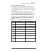
Figure 8-3 Serial Port Pin Assignments
Serial Port 9 Configuration
Table 8-1 on page 231 and the following paragraphs describe how to
configure Serial Port 9 for communications with an external PC or
terminal. Implications of the various choices are discussed.
1. Under the To Screen menu, select More, then select
IO CONFIG.
2. The I/O CONFIGURE screen will be displayed.
3. Set the Serial Baud Rate, Parity, Data Length, Stop Length,
Rcv Pace and Xmt Pace fields to match your PC or terminal
settings. The recommended settings are shown in Table 8-1 on page
231. These settings will be retained by the Test Set. They will not
change if the PRESET key is pressed, if the Test Set receives a *RST
Common Command, or the power is turned on and off.
4. Set the Serial In field to Inst. This routes Serial Port 9 to the
IBASIC Command Line field. Characters typed on the external PC or
terminal will now appear in the IBASIC Command Line.
5. Set the IBASIC Echo field to ON. This will cause IBASIC character
output from commands (such as LIST, PRINT or DISPLAY) or error
messages to echo characters to Serial Port 9 (the characters will in
turn show up on the external PC or terminal screen). This will allow
program listings and syntax error messages to be seen on the
external PC or terminal.
Table 8-1 Serial Port Pin Assignment
Pin Description
1 CD - Carrier Detect
2 RD - Receive Data
3 TD - Transmit Data
4 DTR - Data Terminal Ready
5 Ground
6 DSR - Data Set Ready
7RTS - Request to Send
8CTS - Clear to Send
9RI - Ring Indicator
5
1
9
6