
Specifications


192 Chapter 8
Performance Tests
RF Generator Level Accuracy Performance Test 5
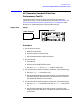
Figure 8-10 Setup 2 for Measurements of 1700 and 2000 MHz
Procedure 2
Steps 1 to 5 in the following procedure apply to Setup 1 shown in Figure
8-9 on page 190.
1. Connect the sensor module on the measuring receiver to the
DUPLEX OUT port of the Test Set.
2. On the Test Set:
a. Set the Amplitude to -10 dBm.
b. Set the RF Gen Freq to 1700 MHz.
3. On the measuring receiver:
a. Set the measurement mode to RF power.
b. Key in 1700 MHz.
c. Measure and record the RF power at the DUPLEX OUT port.
4. On the Test Set set the RF Gen Freq to 2000 MHz.
5. On the measuring receiver:
a. Key in 2000 MHz.
b. Measure and record the RF power at the DUPLEX OUT port.
Steps 6 to 8 apply to Setup 2 shown in Figure 8-10 on page 192.
6. Make the connections shown in Setup 2.
DUPLEX OUT
Measuring Receiver
INPUT 50Ω
IF OUTPUT
LO RF
RF
INPUT
INPUT OUTPUT
Signal Generator
Microwave
Converter
INPUT
OUTPUT
AMPLIFIER 1
RF IN/OUT