Operating Manual Agilent Technologies 8757D Scalar Network Analyzer Manufacturing Part Number: 08757-90109 Printed in USA Print Date: March 2005 Supersedes: November 2000 © Agilent Technologies, Inc.
Hewlett-Packard to Agilent Technologies Transition This manual may contain references to HP or Hewlett-Packard. Please note that Hewlett-Packard's former test and measurement, semiconductor products and chemical analysis businesses are now part of Agilent Technologies. To reduce potential confusion, the only change to product numbers and names has been in the company name prefix: where a product number/name was HP XXXX the current name/number is now Agilent XXXX.
Printing Copies of Documentation from the Web To print copies of documentation from the Web, download the PDF file from the Agilent web site: • Go to http://www.agilent.com. • Enter the document’s part number (located on the title page) in the Quick Search box. • Click GO. • Click on the hyperlink for the document. • Click the printer icon located in the tool bar.
Contacting Agilent This information supersedes all prior HP contact information. Online assistance: www.agilent.
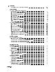
Contents Table of Contents 1. General Information Safety Considerations . . . . . . . . . . . . . . . . . . . . . The HP 8757D Analyzer . . . . . . . . . . . . . . . . . . . . CRT/LCD Attributes . . . . . . . . . . . . . . . . . . . . Displays . . . . . . . . . . . . . . . . . . . . . . . . . . Peripherals . . . . . . . . . . . . . . . . . . . . . . . . . Calibration Data and Instrument States . . . . . . . . . . . . Measurement Channels . . . . . . . . . . . . . . . . . . . Local and Remote Operation . .
3. Operation HP/Agilent 8757D Firmware Capability . . . . . . . . . . . . . . . . Local Operation HP 8757D User's Guide (wire-o book) . . . . 1. Operating . . . . . . . . . . . . . . 2. Transmission Measurements . . . . . . 3. Re ection Measurements . . . . . . . 4. Limit Lines . . . . . . . . . . . . . 5. Alternate Sweep . . . . . . . . . . . 6. External Disk Save/Recall . . . . . . . 7. Special Functions . . . . . . . . . . . A. AC versus DC Detection . . . . . . . Index . . . . . . . . . . . . . . . .
Autozero of DC Detectors . . . . . . . Save/Recall Registers . . . . . . . . . System Interface On/O . . . . . . . . Measurement-Memory-Memory . . . . . Cursor Search . . . . . . . . . . . . On-Site Service . . . . . . . . . . . . . Main Error Codes . . . . . . . . . . . Power Calibration Error Messages . . . . Detector Error Messages (HP 85037A/B only On-Site Service - Calibration . . . . . . . . . . . . . . . . . . . . . . . . . . . . . . . . . . . . . . . . . . . . . . . . . . . . . . . . . . . . .
1 General Information This chapter provides information on the following topics: general safety considerations serial numbers analyzer description power calibrator option available options speci cations operating characteristics manufacturer's radio interference declaration manufacturer's sound emission declaration manufacturer's ISO declaration ordering accessories and supplies General Information 1-1
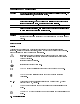
General Safety Considerations Warning No operator serviceable parts inside. Refer servicing to qualified personel. To prevent electric shock, do not remove covers. Warning To prevent electrical shock, disconnect the Agilent Technologies 8757D from mains before cleaning. Use a dry cloth or one slightly dampened with water to clean the external case parts. Do not attempt to clean internally. Warning If this product is not used as specified, the protection provided by the equipment could be impaired.
The AC symbol is used to indicate the required nature of the line module input power. The C-Tick mark is a registered trademark of the Australian Spectrum Management Agency. Warning The WARNING sign denotes a hazard. It calls attention to a procedure, which, if not correctly performed or adhered to, could result in personal injury. Do not proceed beyond a WARNING sign until the indicated conditions are fully understood and met. Caution A Caution note denotes a hazard.
Preface This manual applies directly to all HP/Agilent 8757D network analyzers. See the serial number plate (Figure 1-1) attached to the analyzer back panel. The rst four digits followed by a letter are the serial number pre x. The last ve digits are the sequential su x, which are unique to each instrument. Figure 1-1.
Figure 1-2.
The HP 8757D Analyzer The HP 8757D (Figure 1-2) is a microprocessor-based receiver capable of making scalar (magnitude only) re ection and transmission measurements. The external detectors used determine the frequency range. The raster display provides high resolution for viewing measurements. The original HP 8757D incorporated a cathode ray tube (CRT) based display. Note The current design incorporates a liquid crystal display (LCD) based display.
Options Available Option 001 adds a fourth detector input (C). Option 002 adds the power calibrator. Option 001 and 002 adds both the fourth detector input and the power calibrator. (See the front panel options table on the following page and the descriptions below it for more detailed information on these options.) Figure 1-3. Option 001, Fourth Detector Input This option supplies four front-panel detector inputs (A, B, C, and R).
Option W30, Extended Service This option (identi ed on the serial number tag) adds two additional years of return-to-HP hardware support following the rst year of warranty. You can order this option only at time-of-purchase. Option W32, Three-Year Calibration This option (identi ed on the serial number tag) provides a three-year return-to-HP calibration service. You can order this option only at time-of-purchase.
Specifications, General Requirements, and Operating Characteristics Specifications Speci cations (listed in Table 1-1) are the performance standards or limits against which the instrument is tested. Speci cations apply from +20 C to +30 C (unless otherwise noted), and only after the instrument's temperature stabilizes after one hour of continuous operation. Unless otherwise noted, corrected limits are given when speci cations are subject to optimization with error-correction routines.
Table 1-1. HP 8757D Specifications1 (1 of 2) Function : Four indep endent display channels pro cess signals from the HP 85025, 85026, 11664, or 85037 detectors and the HP 85020 or 85027 bridges. The analyzer displays the data logarithmically, in single input or ratio mode, with resp ect to frequency, on the internal CRT/LCD. Three detector inputs (A, B, and R) accept AC or DC detected signals from detectors or bridges. Option 001 has four detector inputs (A, B, C, and R).
HP 8757D Specifications1 (2 of 2) Power Calibrator (Option 002) The internal power calibrator option (Option 002) provides a 50 MHz reference standard for characterizing the absolute power accuracy and dynamic power accuracy of HP 85037 Series precision detectors. Frequency : 50 MHz Output Power 60.1 MHz (DC mode): 050 Range: +20 to Accuracy at 0 dBm: 60.05 dB SWR: 1.
Table 1-2. HP 8757D General Requirements General requirements de ne speci cations required of the source for proper analyzer operation.
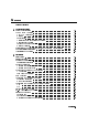
Table 1-3. Operating Characteristics1 (1 of 4) Display Display Modes: All analyzer channels can display any detector input, or any ratio combination of detector inputs. The CRT/LCD can display data in one of the following modes. Log Magnitude: dBm: dB: Single channel power measurement. Relative power measurement (ratio or relative to trace memory). SWR: Relative measurements. AUX: The rear-panel BNC input ADC IN can be measured and displayed in volts (010 to +10V). Typical maximum error is 60 mV.
Table 1-3. Operating Characteristics1 (2 of 4) Display(cont'd) Horizontal Resolution: Number of Traces 1 2 3, 4 Averaging : Number of Points 101, 201, 401, 801, 1601 101, 201, 401, 801 101, 201, 401 2, 4, 8, 16, 32, 64, 128, or 256 successive traces. Smoothing: Provides a linear moving average of adjacent data points. The smoothing aperture de nes the trace width (number of data points) averaged, and ranges from 0.1% to 20% of the trace width.
Table 1-3. Operating Characteristics1 (3 of 4) LCD/CRT and Graphics CRT Scan Rate: Raster scan with 60 Hz vertical refresh rate, and 25.5 CRT Graphics Resolution: 1024 horizontal x 400 vertical pixels. LCD Scan Rate: Raster scan with 59.83 Hz vertical refresh rate LCD Graphics Resolution: 640 horizontal x 480 vertical pixels. ADC IN: An auxiliary voltage input kHz horizontal scan rate. and 31.41 kHz horizontal scan rate.
Table 1-3. Operating Characteristics1 (4 of 4) HP-IB Interface: HP-IB operates according to IEEE 488-1978 and IEC-625 interface standards. Note that the HP-IB interface does not support the IEEE 488.2 standard. Interface Function Codes: SH1, AH1, T6, TE0, L4, LE0, SR1, RL1, PP0, DC1, DT0, C0, E1. Transfer Formats: You may transfer data either as ASCII characters, or as 16-bit integers (most signi cant byte rst). You may take readings at a single point, or transfer an entire trace at once.
Caution This product is designed for use in INSTALLATION CATEGORY II AND POLLUTION DEGREE 2, per IEC 61010-1 and 664 respecitively. Manufacturer's Declarations RADIO FREQUENCY INTERFERENCE Note This is to certify that this product meets the radio frequency interference requirements of Directive FTZ 1046/1984. The German Bundespost has been noti ed that this equipment was put into circulation and has been granted the right to check the product type for compliance with these requirements.
SOUND EMISSION Note This statement is provided to comply with the requirements of the German Sound Emission Directive, from 18 January 1991. This product has a sound pressure emission (at the operator position) <70 dB. Sound Pressure Lp <70 dB (A). At Operator Position. Normal Operation. According to ISO 7779 (Type Test). Model HP/Agilent 8757D Note Herstellerbescheinigung Diese Information steht im Zusammenhang mit den Anforderungen der Maschinenlarminformationsverordnung vom 18 Januar 1991.
General Information 1-19
Accessories and Supplies See Figure 2-2, \Example of a Static-Safe Workstation," and Table 1-4 for a list available parts. To order a listed item, provide the part number and the quantity required; send the order to the nearest Agilent Technologies sales and service o ce, listed at the back of this chapter.
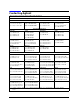
Table 1-4. Replaceable Parts for the HP/Agilent 8757D Description HP/Agilent Part Number Documentation Manual Set (includes 08757-90109 and 08757-90110) Operating Manual (includes programming guides) Programming Guides: HP 9000 Series 200/300 HP Vectra Microsoft Quick Basic 4.5 HP Vectra Microsoft C 2.
Table 1-5. Agilent Technologies Sales and Service Offices UNITED STATES Instrument Support Center Agilent Technologies (800) 403-0801 EUROPEAN FIELD OPERATIONS Headquarters France Germany Agilent Technologies S.A. Agilent Technologies France Agilent Technologies GmbH 150, Route du Nant-d'Avril 1 Avenue Du Canada Agilent Technologies Strasse 1217 Meyrin 2/Geneva Zone D'Activite De Courtaboeuf 61352 Bad Homburg v.d.H Switzerland F-91947 Les Ulis Cedex Germany (41 22) 780.
2 Installation This chapter provides information on the following topics: initial inspection instrument serial numbers environmental requirements electrostatic discharge hazards and precautions line voltage selector switch fuse inspection power cable inspection Introduction This section provides installation instructions for your HP/Agilent 8757D scalar network analyzer.
Initial Inspection Inspect the shipping container for damage. If the shipping container or cushioning material is damaged, keep it until you have veri ed that the contents are complete and you have tested the analyzer mechanically and electrically. If the shipment is incomplete or if the analyzer does not pass the operator's check (see chapter 3) notify the nearest Agilent o ce. If the shipping container is damaged or the cushioning material shows signs of stress, notify the carrier.
Figure 2-1. Typical Serial Number Label Operating Environment Caution VENTILATION REQUIREMENTS: When installing the product in a cabinet, the convection into and out of the product must not be restricted. The ambient temperature (outside the cabinet) must be less than the maximum operating temperature of the product by 4 C for every 100 watts dissipated in the cabinet. If the total power dissipated in the cabinet is greater than 800 watts, then forced convection must be used.
Electrostatic Discharge Because electrostatic discharge (ESD) can damage or destroy electronic components, perform all work on assemblies consisting of electronic components at a static-safe work station. Static-Safe Accessories See chapter 1 \General Information" for static-safe accessories available from Agilent Technologies. Figure 2-2 is an example of a static-safe work station using two types of ESD protection that can be used either together or separately: 1.
Power Requirements Table 2-1.
Figure 2-3. Setting the Voltage Selector Switch and Checking the Fuse Checking the Power Cable The analyzer is shipped with a three-wire power cable (appropriate for its original destination), in accordance with international safety standards. When connected to an appropriate power line outlet, this cable grounds the analyzer chassis. Warning This is a Safety Class 1 Product (provided with a protective earthing ground incorporated in the power cord).
Equipment Required But Not Supplied To make measurements with a standard analyzer, you must have a swept RF or microwave source and from one to three detectors or directional bridges (four with an Option 001). AC Detection AC detection measurements require square wave modulation capability at 27.778 kHz. Firmware Compatibility Table 2-3 lists the sweeper rmware revisions required for complete compatibility with the HP/Agilent 8757D. Table 2-3.
Rack Mounting Caution Use only the speci ed screws to install the rack mount kit. Longer screws can damage internal components located behind the screw mounting holes. Rack Mounting without Front Handles (Option 908) Option 908 instruments are shipped with a rack mount kit. The kit supplies the hardware and installation instructions to prepare the instrument to mount on an equipment rack with 482.6 mm (19 in) support spacing. To order additional rack mount kits, see Table 1-4. 1. Refer to Figure 2-4.
Figure 2-4.
Connecting the Analyzer to a Source Figure 2-5, Figure 2-6, Figure 2-7, and Figure 2-8 show the interconnections between the analyzer and three commonly used sources. External Modulation Unlike the HP/Agilent 8350, 8360, and 83750 Series sources, HP/Agilent 8340 and 8341 Series synthesizers do not provide an internal 27.778 kHz modulated signal (used in AC measurements). Use the analyzer's 27.778 kHz modulation signal to externally modulate the source, connected as described in Table 2-4. Table 2-4.
Figure 2-5.
Figure 2-6.
Figure 2-7.
Figure 2-8.
Figure 2-9.
Connecting the Analyzer to an External Monitor CRT Use the three rear panel outputs (RGB) to drive an external monitor (see chapter 1 for speci c video output characteristics). Connect the three BNC analyzer outputs (RGB) to the corresponding monitor inputs. If you use a monochrome monitor, operate the analyzer in monochrome mode and connect only the green (G) output to the monitor. LCD The analyzer can drive both its internal display and an external monitor simultaneously.
Checking the Address To display the current HP-IB address on the CRT: 1. Press 4LOCAL5. 2. Select 8757 . NNNNNNNNNNNNNN Changing the Address To change the HP-IB address: 1. Press 4LOCAL5. 2. Select 8757 . The CRT displays the current address. 3. Using the front panel keypad, enter the new address. 4. Press 4ENT5 to terminate the entry. The CRT displays the new address. Turning the line switch o or presetting the instrument does not a ect this address.
HP-IB Connectors and Cables A tutorial description of HP-IB is available from Agilent Technologies (see chapter 1 for ordering information). See also \Remote Operation," which describes the analyzer's HP-IB capabilities. Figure 2-11 illustrates an HP-IB connector pin con guration and signals. Connectors The analyzer has two rear panel HP-IB connectors: 1. The 8757 System Interface (J1).
Figure 2-11.
Storing and Shipping Environment Store or ship the instrument in environments within the following limits: Temperature : : : : : : : : : : : : : : : : : : : : : : : : : : : : : : : : : : : : : : : : : : : : 040 to + 70 C (040 to + 167 F) Altitude : : : : : : : : : : : : : : : : : : : : : : : : : : : : : : : : : : : : : : : : : : : : : : : : : : : : : 15,240 metres (50,000 feet) Humidity : : : : : : : : : : : : : : : : : : : : : : : : : : : : : : : : : : : : : : : : : : : : : : : : : : : : : : : : 90% at
When making inquiries, either by correspondence or by telephone, please refer to the instrument by model number and full serial number.
3 Operation Note The original HP/Agilent 8757D incorporated a cathode ray tube (CRT) based display. The current design incorporates a liquid crystal display (LCD) based display. In this manual, references to either CRT or LCD apply to both display designs unless noted otherwise. The front panel LINE switch disconnects the mains circuits from the mains supply after the EMC lters and before other parts of the instrument. HP/Agilent 8757D Firmware Compatibility Caution Only rmware revisions 5.1 through 6.
Remote Operation (see white tab) For reference only. The three introductory programming guides may refer to osolete hardware and software. This section contains: information on converting HP/Agilent 8757A software quick reference guide introductory programming guides with example programs and programming codes In Case of Difficulty (see white tab) This section contains information on what to do if you encounter a problem with the analyzer.