
Technical data


2-18
Using the 86100C
Optional Features and Licenses
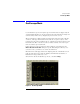
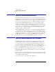
Option 201, Advanced Waveform Analysis
The Advanced Waveform Analysis feature, option 86100C-201, provides two
powerful tools for the design engineer: a Linear Feedforward Equalizer and a
MATLAB Filter. It also includes the abiltiy to import and export pattern wave-
forms. This feature requires that Option 001, Enhanced Trigger, is installed.
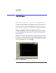
The Linear Feedforward Equalizer allows you to design and apply a finite
impulse response (non-recursive) digital filter to an instrument channel or
math function. With the Linear Feedforward Equalizer, you can model equal-
izer designs on an actual signal before designing any hardware. The equalizer
allows you to open a closed eye diagram on your system with the goal of a
designing a stable, compliant system.
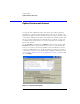
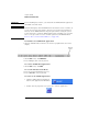
With the MATLAB Filter application, you can design and apply software filters
to a waveform and view the real-time output on the 86100C display. Because
this application uses the product, MATLAB , which is a technical computing
language and environment, you can write your own software filter scripts. The
MATLAB Filter application does not include MATLAB. You must purchase
(www.mathworks.com) and install MATLAB separately on the 86100C.
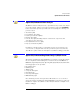
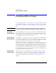
Option 202, Enhanced Impedance and S-Parameter
The Enhanced Impedance and S-Parameter software, option 86100C-202,
adds the ability to measure S-parameters in TDR/TDT Mode. S-parameters
(scattering parameters) are power ratio measurements that describe how a
test device modifies a signal. Typical S-parameter measurements include
return loss, insertion loss (attenuation), near-end cross talk (NEXT), and far-
end cross talk (FEXT). This software provides the following capabilities:
• Fast-Fourier Transform of the TDR time-domain data into the frequency do-
main. The resulting S-parameter data is displayed on a Cartesian logarithmic
magnitude graph.
• Export S-parameter data (including phase information) to Touchstone format
files. Touchstone files can be imported into Agilent's Physical Layer Test Sys-
tems (PLTS) for further analysis.
• Correct the impedance profile (peeling) of TDR traces.