
Technical data


4-36
Replacing Instrument Assemblies
A13 Acquisition Board PLD Header Modification (86100A Only)
A13 Acquisition Board PLD Header Modification
(86100A Only)
Refer to ”Preventative Maintenance” on page 1-17 in “General Information” for serial prefix
information.
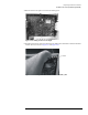
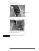
1 Follow the instructions for removing the mainframe cover, on page 4-4.
2 Follow the instructions for removing the A13 Acquisition Board, on page 4-32.
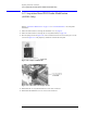
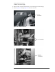
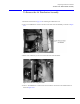
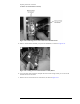
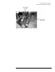
3 Place the jumper, shown in Figure 4-56, on P12 so that the resistors are connected to pins 1, 4, and
5, shown in Figure 4-57. The jumper key should face towards the front panel.
Figure 4-56. Jumper, E2660-01201
Figure 4-57. Placement of the Jumper on P12
4 Reassemble the A13 Acquisition Board in reverse order of removal.
5 Reassemble the Mainframe Cover in reverse order of removal.