
Technical data


3-4
Adjustments
86100A/B Mainframe Timebase Adjustment
a Turn on the timebase EXT and EXT DIVIDE, and set to divide by one.
b Set the CHANNEL 2 output as follows:
SQUAR ON
AMPL 2.4 V
OFFS 0 (If needed, adjust the offset to center the output around 0 V.)
DISABLE OFF
c Set all other controls to zero or off.
3 On the synthesized CW generator, press PRESET, then set the controls as follows:
FREQ 500 MHz
POWER LEVEL -14 dBm
RF ON/OFF OFF
NOTE If the Synthesized CW Generator does not have Option 1E1 installed, insert a 10 or 20 dB
attenuator at the RF OUTPUT and set the POWER LEVEL so that the power going to the
electrical channel is -14 dBm. (Example: 10 dB attenuator = -4 dBm; 20 dB attenuator =
+6 dBm.)
4 Install the plug-in module into the mainframe left-hand module slot, then tighten both screws.
5 Turn on the mainframe. After the boot-up is complete, press the Default Setup hardkey on the
DCA front panel.
6 Turn on the electrical channel by pressing the CHANNEL 2 hardkey on the DCA front panel.
Turn all other channels off.
7 On the DCA front panel, set the trigger source to Free Run by pressing the Source hardkey until
Free Run is selected.
NOTE Allow all of the equipment to warm up for at least one hour in the settings specified above
before you proceed.
8 Ensure that everything is disconnected from the electrical plug-in input.
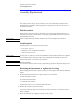
9 On the DCA screen, press Calibrate, All Calibrations, Vertical (Amplitude), Calibrate Left
Module, then press Continue.
10 Wait for the completion of the calibration routine.
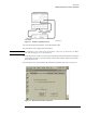
11 Connect equipment as shown in Figure 3-1.
a Connect the synthesized CW generator’s 10 MHz OUT to the timing generator’s timebase EX-
TERNAL INPUT.
b Connect the 2000 ps transition time converter to the timing generator’s CHANNEL 2 output.
c Connect the 2000 ps transition time converter to the DCA front panel trigger input, using the
cable and adapters.
d Connect the synthesized CW generator RF OUTPUT to the module electrical channel.