
Technical data


2-23
Performance Verification
Trigger Verification (Standard and Option 001)
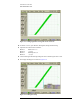
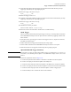
18 Adjust the delay knob counterclockwise so that the first rising zero crossing point intersects the
center of the display. Refer to Figure 2-17 below.
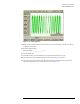
Figure 2-17. Divided Trigger Screen
19 Press Clear Display and wait for the reading to finish.
At higher frequencies it can take several seconds before enough data is collected.
20 Record the Jitter RMS in the Performance Test Record.
21 Repeat Step 10 through Step 20 for each Synthesized CW Generator FREQ setting. Set the DCA’s
power level and horizontal scale to the corresponding settings, as shown in Table 2-4, below.
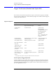
Table 2-4. Synthesizer and DCA Horizontal Scale Settings
Column 1 Column 2 Column 3
Synthesizer FREQ (GHz) Synthesizer POWER LEVEL (dBm) DCA Horizontal Scale (ps/div)
23.8 20
2.5 3.9 20
55.6 5
10 7.3 2
12 7.7 2