
Technical data


2-21
Performance Verification
Trigger Verification (Standard and Option 001)
17 On the DCA front panel, adjust the Trigger Level knob clockwise until the DCA just stops
triggering as indicated by the Trig’d light going off.
18 Record the trigger value below as V pos:
V pos _____________ mV
19 Return the Trigger Level to 0 V.
20 On the DCA front panel, adjust the Trigger Level knob counterclockwise until the DCA just stops
triggering as indicated by the Trig’d light going off.
21 Record the trigger value below as V neg:
V neg _____________ mV
22 Calculate the sensitivity as follows:
Vsense 2.5 GHz = 200 mV − (V pos − V neg)
23 Record the result in the Performance Test Record as 2.5 GHz Sensitivity.
Gated Trigger
This test verifies the functionality of the gated trigger circuitry by connecting a BNC termination
to the TRIGGER GATE input on the rear panel. The DCA should stop triggering with this termi-
nation attached.
1 On the DCA screen, press Trigger Level and set the trigger level to 0 V, Hysteresis to Normal,
and enable the Gated Trigger.
2 Confirm that the DCA is triggered as indicated by the lit Trig’d light.
3 Connect a BNC termination to the TRIGGER GATE input on the DCA’s rear panel.
4 Check that the DCA is not triggered as indicated by the Trig’d light going off.
Option 001 Divided Trigger Sensitivity
NOTE Perform this test only if the Agilent 86100A/B has option 001 installed. To see if option 001
is installed, touch/click Help, About. Option 1: 12.5 GHz will be displayed next to the serial
number.
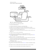
1 Connect the equipment as shown in Figure 2-16.
a Connect the Synthesized CW Generator’s OUTPUT to the INPUT of a Power Splitter.
b Connect one output port of the Power Splitter to the Delay Line.
c Connect the other output port of the Power Splitter to the INPUT of a second Power Splitter.
d Connect one output port of the second Power Splitter to channel two of the electrical module.
e Connect the other output port of the second Power Splitter to the DCA trigger input.
f Connect the Delay Line to channel one of the electrical module.