
Technical data


2-19
Performance Verification
Trigger Verification (Standard and Option 001)
Procedure
1 Warm up the system for at least 60 minutes, before verifying performance.
2 Disconnect everything from the channel inputs on the DCA.
3 On the DCA screen, press Calibrate, All Calibrations, Vertical (Amplitude), and Calibrate Left
Module.
4 Wait for the completion of the vertical calibration.
5 Set the Function/Arbitrary Waveform Generator as follows:
a Set the Frequency to a 100 kHz sine wave
b Set the output to 180 mV pp
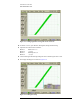
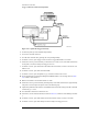
6 Connect the equipment as shown in Figure 2-15.
a Connect the Function/Arbitrary Waveform Generator’s OUTPUT to the Power Splitter’s
INPUT.
b Connect one output port of the Power Splitter to the DCA front panel trigger input.
c Connect the other output port of the Power Splitter to the desired module electrical channel.
Figure 2-15. Trigger Sensitivity Equipment Setup
7 On the front panel, press the Default Setup hardkey.
8 Ensure that the correct channel is enabled.
9 Turn all other channels off.
10 On the DCA screen, press Scale Offset for the channel in use, then set the scale (vertical) to
20 mV/div and the offset to 0.0 V.
11 On the DCA screen, press Time Delay, set the Scale (horizontal) to 1 µs/div.
12 On the DCA screen, press Setup, Acquisition, Enable Averaging.
13 On the DCA screen, press Amplitude then V p-p.
14 On the Function/Arbitrary Waveform Generator, adjust the output level for a 100 mV p-p ± 1 mV
reading on the DCA.
15 Adjust the Trigger Level knob clockwise until the DCA just stops triggering, as indicated by the
Trig’d light going off.