
Technical data


2-18
Performance Verification
Trigger Verification (Standard and Option 001)
Trigger Verification (Standard and Option 001)
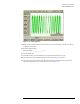
The sensitivity test measures the high and low frequency sensitivities by applying a 100 MHz
sine wave and a 2.5 GHz sine wave. If the oscilloscope triggers at 2.5 GHz, it will also trigger on
a 200 ps pulse width at 200 mV.
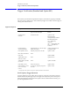
Equipment Required
Equipment Critical Specifications Recommended Model/Part
Plug-in Module 54750A, 82480A, or 86100A/B series
plug-in with electrical input
Agilent 54751A, 83483A,
86112A
Synthesized CW
Generator
10 MHz to 20 GHz Agilent 83712B
Required Options:
1E5 High Stability Timebase
Recommended Options:
1E1— Output Step
Attenuator
1E8 — 1 Hz Frequency Res.
1E9 — 3.5 mm RF Out
Connector
Function/Arbitrary
Waveform Generator
10 MHz square wave, 120 mV output,
stability 0.05 ppm/yr
Agilent 3325B Option 001
or Agilent 33250A
Power Splitter (2 each) Frequency range of dc to 18 GHz
Agilent 11667B
a
a. Testing Option 001 requires an extra power splitter and a dual electrical module
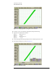
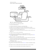
Low Frequency Trigger Hysteresis
A signal is applied to a power splitter whose outputs are connected to the module’s electrical
channel and the front panel trigger input. The trigger level is adjusted to positive and negative
until it stops triggering. These positive and negative values are subtracted from 100 mV p-p to
give the Trigger Hysteresis value.
BNC (male) Termination
50
Ω
Delay Line Agilent 54008B
Adapter, BNC (m) to
SMA (m) (2 each)
50
Ω
Agilent E9633A
Adapter, BNC (f) to BNC
(f) (2 each)
50
Ω
Agilent 1250-0080
Cable, BNC (2 each)
50
Ω,=122 cm (48 in)
Agilent 10503A
Cable Assembly, 3.5 mm
(m) to 3.5 mm (m)
(4 each)
61 cm (24 in); Frequency range dc to
26.5 GHz
Agilent 11500E