
Technical data


2-13
Performance Verification
Jitter Performance Test
Jitter Performance Test
Jitter is measured at 2.5 GHz with the triggering level adjusted for optimum trigger. The jitter
test measures the oscilloscope’s internal jitter on a 2.5 GHz sine wave. The instrument’s jitter is
less with fast rise time input signals.
A 24 ns delay line is added to delay the input signal so that the trigger point is on screen. The
delay setting is determined and used to calculate the specification limit. A histogram is used to
increase the accuracy of the RMS jitter measurement.
NOTE The 86100A/B DCA has an additional 2 ns of delay compared to the Agilent 83480A or
83750A.
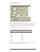
Equipment Required
Procedure
1 Warm up the system for at least 60 minutes, then perform a vertical calibration.
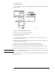
2 Connect the equipment as shown in Figure 2-11.
a Connect the synthesized CW generator’s OUTPUT to the Power Splitter’s INPUT.
b Connect one output port of the Power Splitter to the DCA front panel trigger input.
c Connect the other output port of the Power Splitter to the Delay Line.
d Connect the Delay Line to the desired module electrical channel.
Equipment Critical Specifications Recommended Model/Part
Plug-in Module 54750A, 82480A, or 86100A/B series
plug-in with electrical input
Agilent 54751A, 83483A,
86112A
Synthesized CW
Generator
Agilent 83712B
Required Options:
1E5 High Stability Timebase
Recommended Options:
1E1— Output Step
Attenuator
1E8 — 1 Hz Frequency Res.
1E9 — 3.5 mm RF Out
Connector
Delay Line 24 ns Agilent 54008B
Power Splitter Frequency range of dc to 18 GHz Agilent 11667B
Cable, BNC
50
Ω, 122 cm (48.in)
Agilent 10503A
Adapter, BNC (m) to
SMA (m)
50
Ω
Agilent E9633A BNC (m) to
SMA (m), 50
Ω
Cable Assembly, 3.5 mm
(m) to 3.5 mm (m) (3
each)
61 cm (24 in); Frequency range of dc
to 26.5 GHz
Agilent 11500E