
Technical data


2-9
Performance Verification
Time Interval Accuracy Performance Test
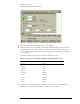
Figure 2-8. Setting Trigger Level for Measuring Time Interval Accuracy
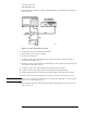
22 Connect the equipment as shown in Figure 2-9.
Figure 2-9. Time Interval Accuracy Setup from 20 ns/div to 20 µs/div
Time Interval Accuracy 20 ns/div to 20µs/div
23 Set the Waveform Generator’s frequency to 10 MHz; set the amplitude to 400 mV pp, offset 0V,
square wave.
24 On the DCA screen, press Time Delay. Ensure that the delay is set to 24 ns, then check the period
at the Function/Arbitrary Waveform Generator and scale settings shown in Table 2-3 and record
them in the Performance Test Record.
25 Press the Clear Display hardkey before recording the new reading.