
Technical data


2-8
Performance Verification
Time Interval Accuracy Performance Test
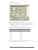
Figure 2-7. Setting Best Sensitivity for Measuring Time Interval Accuracy
19 Select the Best Sensitivity Sampler Bandwidth. Close dialog box.
20 On the DCA screen, press Time Delay, then check the period at the scale and synthesized CW
generator settings shown in Table 2-2 and record the results in the Performance Test Record.
a Press the Clear Display hardkey and wait for the averaging to complete before recording the
current results.
b Adjust the vertical scale as necessary to keep the signal on the screen.
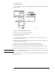
21 On the DCA screen, press Trigger Level and set the Trigger Level to 500 mV. See Figure 2-8.
Alternatively use the Trigger knob and adjust the Trigger Level to 500 mV.
Table 2-2. Period Accuracy for Horizontal Scale Settings from 20 ps to 10 ns
Horizontal Scale Setting Synthesized CW Generator Setting
20 ps/div 10 GHz
50 ps/div 5 GHz
100 ps/div 2 GHz
200 ps/div 1 GHz
500 ps/div 500 MHz
1 ns/div 200 MHz
2 ns/div 100 MHz
5 ns/div 50 MHz
10 ns/div 20 MHz