
Technical data


2-4
Performance Verification
Time Interval Accuracy Performance Test
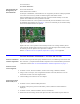
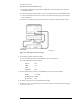
a Connect the synthesized CW generator’s 10 MHz OUT to the timing generator’s timebase
EXTERNAL INPUT.
b Connect the 2000 ps transition time converter to the timing generator’s CHANNEL 2 output.
c Connect the 2000 ps transition time converter to the DCA front panel trigger input, using the
cable and adapters.
d Connect the synthesized CW generator OUTPUT to the desired module electrical channel.
Figure 2-1. Time Interval Accuracy Setup
3 Set the timing generator controls as follows:
a Turn on the timebase EXT and EXT DIVIDE, and set to divide by one.
b Set the CHANNEL 2 output as follows:
SQUAR ON
AMPL 2.5 V
OFFS 0
DISABLE OFF
4 On the synthesized CW generator, press PRESET, then set the controls as follows:
FREQ 19.98 GHz
POWER LEVEL 0 dBm
RF ON/OFF OFF
5 On the DCA front panel, press the Default Setup hardkey.
6 On the DCA screen, press Time Delay, set the scale to 10 ps/div, and set the Delay From Trigger
to 24 ns. See Figure 2-2.