
Technical data


2-3
Performance Verification
Time Interval Accuracy Performance Test
Time Interval Accuracy Performance Test
The horizontal time interval accuracy of the mainframe and plug-in modules are compared to a
known reference.
Equipment Required
Period Accuracy for Delay Settings
Procedure
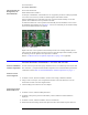
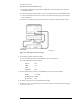
1 Warm up the system for at least 60 minutes, then perform a vertical calibration.
2 Connect the equipment as shown in Figure 2-1.
Equipment Critical Specifications Recommended Model/Part
Plug-in Module 54750A, 82480A, or 86100A series
plug-in with electrical input
Agilent 54751A, 83483A,
86112A
Synthesized CW
Generator
No substitution Agilent 83712B
Required Options:
1E5 High Stability Timebase
Recommended Options:
1E1— Output Step
Attenuator
1E8 — 1 Hz Frequency Res.
1E9 — 3.5 mm RF Out
Connector
Timing Generator No substitution Agilent 8133A standard or
Option 002
Function/Arbitrary
Waveform Generator
10 MHz square wave, 120 mV output,
stability 0.05 ppm/yr
Agilent 3325B Option 001
or Agilent 33250A
Transition Time Converter 2000 ps Agilent 15438A
Cable, BNC
50
Ω, 122 cm (48.in)
Agilent 10503A
Adapter, BNC (m) to
SMA (m)
50 Ω
Agilent E9633A BNC (m) to
SMA (m), 50
Ω
Cable Assembly, 3.5 mm
(m) to 3.5 mm (m) (2
each)
61 cm (24 in); Frequency range of dc
to 26.5 GHz
Agilent 11500E
Adapter, 3.5 mm (f) to 3.5
mm (f) (2 each)
dc to 34 GHz Agilent 1250-1749