
Technical data


2-2
Performance Verification
Performance Verification
Performance Verification
This chapter documents the performance tests. Equipment required for individual tests is listed in
the test descriptions in this chapter. Equipment satisfying the critical specifications listed may be
substituted for the recommended model.
Performance Testing
Interval
The performance test procedures may be performed for incoming inspection of the instrument
and should be performed periodically thereafter to ensure and maintain peak performance. The
recommended test interval is yearly or every 2,000 hours of operation.
Specifications The specifications that apply to a particular test are listed in chapter 1 of this manual. Refer to the
86100A/B on-line help for specifications.
Performance Test
Record
You may record the results of the performance tests in the Performance Test Record provided at
the end of this chapter. The Performance Test Record lists the performance tests and provides an
area to mark test results. You can use the results recorded at incoming inspection for later com-
parisons during periodic maintenance, troubleshooting, and after repairs or adjustments.
Before Testing
• Warm up the system for at least 60 minutes prior to beginning the performance tests.
• After sufficient warm up, perform a vertical calibration on the system.
• Avoid damage to plug-in front panel connectors. Use 2.4 mm and 3.5 mm connector savers. These
connector savers are a supplied accessory.
• Minimize connector swapping during the procedures to avoid connector wear. All connectors on
test tools and adapters should be inspected both visually and mechanically every few calibrations.
• All connectors should be clean and undamaged to ensure accurate measurements. All 2.4 mm and
3.5 mm connectors should be mechanically and visually checked before inserting any calibration
test tool into them. Damaged connectors or loose connectors may cause the performance verifica-
tion tests to fail.
• Avoid sharp bends in 2.4 mm, 3.5 mm, SMA, and optical cables. When mating 2.4 mm to 2.4 mm
or 3.5 mm to 3.5 mm, torque all connections to 8 in/lbs. When mating 3.5 mm to SMA or SMA
to SMA, torque all connections to 5 in/lbs.
CAUTION The module inputs are very sensitive to static discharge. Failure to observe proper antistatic
procedures may damage the gallium arsenide samplers. ESD damage is not covered under the
warranty. All maintenance or operation should be performed with an antistatic mat and wrist strap.
Refer to “Electrostatic Discharge Information” on page 1-9 for further information.
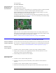
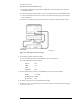
CAUTION Electrostatic discharge can seriously damage the module’s electrical inputs. To eliminate any
electrostatic build up from a cable you’re connecting to the module, connect a female short to
either end of the cable. Touch the short to an input connector hex nut on the module to discharge
any static build up to ground. Remove the short. Use this procedure for all cables before
connecting them to the module.