
Technical data


Index
Index-i
Numerics
86100A/B mainframe timebase ad-
justment
1-18, 3-3
A
A1 power supply removal 4-37
A13 acquisition (option 001) remov-
al
4-11, 4-32, 4-36
A2 flat panel display removal
4-14
A3 backlight inverter removal
4-20
A4 PC motherboard removal
4-25
A6 distribution assembly removal
4-39
A7 front panel keyboard removal
4-18
A8 touch screen removal
4-17
accessories
cleaning
1-5
static-safe
1-9
adjustment interval
3-2
Agilent offices
1-13
B
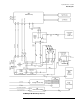
block diagrams
86100A
5-27
86100B
6-27
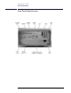
bottom view identification
5-20,
6-20
C
cabinet, cleaning 1-3
cable identification
5-3, 6-3
care
of cabinet
1-3
characteristics
1-14
cleaning
adapters
1-7
fiber-optic connections
1-6
non-lensed connectors
1-6
cleaning accessories
1-5
compressed dust remover
1-5
cotton swabs
1-5
isopropyl alcohol
1-5
small foam swabs
1-5
cleaning optical connectors
1-4
compressed dust remover
1-5
connectors
optical, cleaning
1-4
cotton swabs
1-5
D
direct mail/phone ordering of parts
5-2
, 6-2
display backlights removal
4-15
dry connections
1-4
dust caps
1-5
E
ESD (electrostatic discharge) 1-3,
1-9
F
fiber optics
connectors, covering
1-12
inspecting
1-5
foam swabs
1-5
front inside panel identification
5-8,
5-22, 5-24, 5-26, 6-8, 6-22,
6-24
front panel cal signal
2-11
front panel removed identification
5-10
, 6-10
front panel trigger input removal
4-23
front view identification
5-6, 6-6
G
general reference 1-3
General Safety Considerations
1-iv
I
identification
bottom view
5-20, 6-20
cable
5-3, 6-3
front inside panel
5-8, 5-22,
5-24, 5-26, 6-8, 6-22, 6-24
front panel removed
5-10, 6-10
front view
5-6, 6-6
left and right side
5-14, 6-14
left side removed
5-16, 6-16
major assembly
5-3, 6-3
rear view
5-12, 6-12
right side removed
5-18, 6-18
IEC Publication 1010
iv
index-matching compounds
1-4
inspecting
cables
1-5
visual
1-5
instrument
returning for service
1-11
internal labels
1-3
isopropyl alcohol
1-5
L
labels
internal
1-3
left and right side identification
5-14
, 6-14
left side removed identification
5-16
, 6-16
LS-120 modification
4-12
M
mainframe cover removal 4-4
mainframe front panel removal
4-7
major assembly and cable identifica-
tion
5-3, 6-3
major assembly identification
5-3,
6-3
modification
LS-120
4-12
PLD header
4-36
module inputs
2-2, 3-2
P
packaging for shipment 1-12
part numbers
bottom view
5-20, 6-20
cable
5-3, 6-3
front inside panel
5-8, 6-8
front panel removed
5-10, 6-10
front view
5-6, 6-6
left and right side
5-14, 6-14
left side removed
5-16, 6-16
major assembly
5-3, 6-3
rear view
5-12, 6-12
right side removed
5-18, 6-18
part ordering
mail/phone system
5-2, 6-2
parts
replacing
4-2
performance test
2-2
front panel cal signal
2-11
interval
2-2
time interval accuracy
2-3
performance test record
2-24
PLD header modification
4-36
R
radiation exposure 1-2
rear view identification
5-12, 6-12
recommended test equipment
1-15
removal
A1 power supply
4-37
A13 acquisition (option 001)
4-11
, 4-32, 4-36
A2 flat panel display
4-14
A3 backlight inverter
4-20
A4 PC motherboard
4-25
A6 distribution
4-39
A7 front panel keyboard
4-18
A8 touch screen
4-17
display backlights
4-15
front panel trigger input
4-23
mainframe cover
4-4
mainframe front panel
4-7
replacement procedures
4-2
required tools
iii
returning for service
1-11, 4-2
right side removed identification
5-18
, 6-18
S
safety precautions 1-2
sales and service offices
1-13
serial number entry
1-19
service
returning for
1-11, 4-2
sales and service offices
1-13
service office
1-11
shipping
procedure
1-11
special tools
iii
specifications
1-14