Service Guide Agilent 86100A/B Mainframe
© Copyright 2000-2002 Agilent Technologies All Rights Reserved. Reproduction, adaptation, or translation without prior written permission is prohibited, except as allowed under copyright laws. Agilent Part No. 86100-90047 Printed in USA February 2002 Agilent Technologies Lightwave Division 3910 Brickway Boulevard Santa Rosa, CA 95403, USA Notice. The information contained in this document is subject to change without notice.
Servicing—At a Glance Servicing—At a Glance This manual documents the service and repair of the Agilent 86100A/B to the assembly level. Before servicing the mainframe, you should be aware that amplitude calibration data can only be installed by the factory. Servicing requires special tools The tools listed below are required to repair all versions of the Agilent 86100A/B.
General Safety Considerations General Safety Considerations This product has been designed and tested in accordance with IEC Publication 1010, Safety Requirements for Electronic Measuring Apparatus, and has been supplied in a safe condition. The instruction documentation contains information and warnings which must be followed by the user to ensure safe operation and to maintain the product in a safe condition.
Contents Servicing—At a Glance iii 1 General Information General Reference 1-3 Cleaning Optical Connectors 1-4 Electrostatic Discharge Information 1-9 Returning the Instrument for Service 1-11 Agilent Technologies Service Offices 1-13 Specifications 1-14 Recommended Test Equipment 1-15 Preventative Maintenance 1-17 2 Performance Verification Performance Verification 2-2 Time Interval Accuracy Performance Test 2-3 Front Panel Cal Signal 2-11 Jitter Performance Test 2-13 Trigger Verification (Standard and Op
Bottom View Identification 5-20 Bottom View, Cover Removed, Identification 5-22 Top View, Cover Removed, Identification 5-24 Rear Panel Identification 5-26 Block Diagrams 5-27 6 Replaceable Parts—86100B Major Assembly and Cable Identification 6-3 Front View Identification 6-6 Front Inside Panel Identification 6-8 Front View, Front Panel Removed, Identification 6-10 Rear View Identification 6-12 Left and Right Side Identification 6-14 Left Side, Cover Removed, Identification 6-16 Right Side, Cover Removed, I
1 General Reference 1-3 Cleaning Optical Connectors 1-4 Electrostatic Discharge Information 1-9 Returning the Instrument for Service 1-11 Agilent Technologies Service Offices 1-13 Specifications 1-14 Recommended Test Equipment 1-15 Preventative Maintenance 1-17 General Information
General Information General Information General Information In this chapter, you will find general information on caring for your optical devices. Safety first! Before servicing the mainframe, familiarize yourself with the safety markings on the instrument and the safety instructions in this manual. This instrument has been manufactured and tested according to international safety standards.
General Information General Reference General Reference Whenever you contact Agilent Technologies about your mainframe, have the complete serial number and option designation available. This will ensure you obtain accurate service information. • Refer to Table 1-1 for a list of internal labels. Clean the cabinet using a damp cloth only. Protect against ESD damage Electrostatic discharge (ESD) can damage or destroy electronic components.
General Information Cleaning Optical Connectors Cleaning Optical Connectors Accurate and repeatable measurements require clean connections. Use the following guidelines to achieve the best possible performance when making measurements on a fiber-optic system: • Keep connectors covered when not in use. • Use dry connections whenever possible. • Use the cleaning methods described in this section. • Use care in handling all fiber-optic connectors.
General Information Cleaning Optical Connectors Table 1-2. Cleaning Accessories Item Agilent Part Number Pure isopropyl alcohol — Cotton swabs 8520-0023 Small foam swabs 9300-1223 Compressed dust remover (non-residue) 8500-5262 Table 1-3.
General Information Cleaning Optical Connectors To clean a non-lensed connector CAUTION Do not use any type of foam swab to clean optical fiber ends. Foam swabs can leave filmy deposits on fiber ends that can degrade performance. 1 Apply isopropyl alcohol to a clean, lint-free cotton swab or lens paper. Cotton swabs can be used as long as no cotton fibers remain on the fiber end after cleaning. 2 Before cleaning the fiber end, clean the ferrules and other parts of the connector.
General Information Cleaning Optical Connectors To clean an adapter 1 Apply isopropyl alcohol to a clean foam swab. Cotton swabs can be used as long as no cotton fibers remain after cleaning. The foam swabs listed in this section’s introduction are small enough to fit into adapters. Although foam swabs can leave filmy deposits, these deposits are very thin, and the risk of other contamination buildup on the inside of adapters greatly outweighs the risk of contamination by foam swabs.
General Information Cleaning Optical Connectors Cleaning Electrical Connections The following list includes the basic principles of microwave connector care.
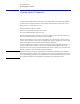
General Information Electrostatic Discharge Information Electrostatic Discharge Information Electrostatic discharge (ESD) can damage or destroy electronic components. All work on electronic assemblies should be performed at a static-safe work station. The following figure shows an example of a static-safe work station using two types of ESD protection: • Conductive table-mat and wrist-strap combination. • Conductive floor-mat and heel-strap combination.
General Information Electrostatic Discharge Information WA R N I N G These techniques for a static-safe work station should not be used when working on circuitry with a voltage potential greater than 500 volts. Table 1-4. Static-Safe Accessories HP Part Number 1-10 Description 9300-0797 3M static control mat 0.6 m × 1.2 m (2 ft × 4 ft) and 4.6 cm (15 ft) ground wire. (The wrist-strap and wrist-strap cord are not included. They must be ordered separately.) 9300-0980 Wrist-strap cord 1.5 m (5 ft).
General Information Returning the Instrument for Service Returning the Instrument for Service The instructions in this section show you how to properly return the instrument for repair or calibration. Always call the Agilent Instrument Support Center first to initiate service before returning your instrument to a service office. This ensures that the repair (or calibration) can be properly tracked and that your instrument will be returned to you as quickly as possible.
General Information Returning the Instrument for Service CAUTION Cover electrical connectors to protect sensitive components from electrostatic damage. Cover optical connectors to protect them from damage due to physical contact or dust. CAUTION Instrument damage can result from using packaging materials other than the original materials. Never use styrene pellets as packaging material. They do not adequately cushion the instrument or prevent it from shifting in the carton.
General Information Agilent Technologies Service Offices Agilent Technologies Service Offices Before returning an instrument for service, call the Agilent Technologies Instrument Support Center at (800) 403-0801, visit the Test and Measurement Web Sites by Country page at http://www.tm.agilent.com/tmo/country/English/index.html, or call one of the numbers listed below. Agilent Technologies Service Offices Austria 01/25125-7171 Belgium 32-2-778.37.
General Information Specifications Specifications Refer to the 86100A/B on-line help for information on mainframe, horizontal (time-base), trigger, and front/rear panel input and output specifications. Touch/click Help, Contents, Specifications for a menu of the desired specifications.
General Information Recommended Test Equipment Recommended Test Equipment The following table is a list of the test equipment required to test performance, calibrate, adjust, and troubleshoot this instrument. The table indicates the critical specification of the test equipment and for which procedure the equipment is necessary. Equipment other than the recommended model may be used if it satisfies the critical specification listed in the table. Table 1-5.
General Information Recommended Test Equipment Table 1-5. Recommended Test Equipment Equipment Required Adapter, 3.5 mm (f) to 3.5 mm (f) (2 each) Critical Specifications Recommended Model Usea DC to 34 GHz Agilent 1250-1749 P a.
General Information Preventative Maintenance Preventative Maintenance The following tasks should be performed at the yearly calibration interval. Perform Mainframe Modification Inspection—86100A Verify that the following modifications have been installed on your 86100A DCA. Intermittent Front Panel Keypads Service Note 86100A-01 Serial Number: US4032 and below Early production units had keypad assemblies with carbon ink on the printed circuit boards together with silver contacts on the rubber keypads.
General Information Preventative Maintenance Plug-in Modules Not Recognized by the DCA Mainframe Service Note 86100A-04 Serial Numbers below US4017: On early DCA mainframes, some modules are not recognized by the DCA. Usually the problem occurs when a clock recovery module is installed together with another module. Various modifications were performed on the A13 Acquisition board assembly to solve this problem. The modifications are not possible in the field.
General Information Preventative Maintenance 5 Check that all keypads are working properly. If any are intermittent, the keypads will need to be replaced. 6 Continue with the Screen Test, Touch Screen, and All Non-interactive. Run Scan Disk 1 On the DCA screen, click/touch Help and About 86100A(or B). 2 On the DCA front panel, press the Local hardkey 5 times (until Service Mode enabled is displayed). 3 On the DCA screen, click/touch Utilities, Service, Exit Scope.
General Information Preventative Maintenance 1-20
2 Performance Verification 2-2 Time Interval Accuracy Performance Test 2-3 Front Panel Cal Signal 2-11 Jitter Performance Test 2-13 Trigger Verification (Standard and Option 001) 2-18 Performance Test Record 2-24 Performance Verification
Performance Verification Performance Verification Performance Verification This chapter documents the performance tests. Equipment required for individual tests is listed in the test descriptions in this chapter. Equipment satisfying the critical specifications listed may be substituted for the recommended model.
Performance Verification Time Interval Accuracy Performance Test Time Interval Accuracy Performance Test The horizontal time interval accuracy of the mainframe and plug-in modules are compared to a known reference.
Performance Verification Time Interval Accuracy Performance Test a Connect the synthesized CW generator’s 10 MHz OUT to the timing generator’s timebase EXTERNAL INPUT. b Connect the 2000 ps transition time converter to the timing generator’s CHANNEL 2 output. c Connect the 2000 ps transition time converter to the DCA front panel trigger input, using the cable and adapters. d Connect the synthesized CW generator OUTPUT to the desired module electrical channel. Figure 2-1.
Performance Verification Time Interval Accuracy Performance Test Figure 2-2. Setting Time and Delay for Measuring Time Interval Accuracy 7 Ensure that the correct channel is enabled. 8 Turn all other channels off. 9 On the DCA screen, press Scale Offset for the channel in use, then set the scale (vertical) to 60 mV/div and the offset to 0 V. See Figure 2-3. Close dialog box. Figure 2-3.
Performance Verification Time Interval Accuracy Performance Test Figure 2-4. Setting Averaging for Measuring Time Interval Accuracy 11 On the Synthesized CW Generator, turn the RF ON/OFF to ON. Figure 2-5. Setting Period for Measuring Time Interval Accuracy 12 On the DCA screen, press Period. See Figure 2-5. 13 On the 86100A/B, adjust the vertical scale so that the signal is on the screen. 14 On the 86100A/B, press the Clear Display hardkey.
Performance Verification Time Interval Accuracy Performance Test 16 On the DCA screen, press Time Delay to set the Delay. See Figure 2-6. After changing the delay, press the Clear Display hardkey before making the next measurement. Table 2-1. Period Accuracy for Delay Settings Delay Setting in ns 24 27.95 35.95 59.95 Figure 2-6. Delay Settings for Measuring Time Interval Accuracy Period Accuracy for Scale Settings 17 On the DCA screen, press Time Delay and set Delay From Trigger to 24 ns.
Performance Verification Time Interval Accuracy Performance Test Figure 2-7. Setting Best Sensitivity for Measuring Time Interval Accuracy 19 Select the Best Sensitivity Sampler Bandwidth. Close dialog box. 20 On the DCA screen, press Time Delay, then check the period at the scale and synthesized CW generator settings shown in Table 2-2 and record the results in the Performance Test Record. a Press the Clear Display hardkey and wait for the averaging to complete before recording the current results.
Performance Verification Time Interval Accuracy Performance Test Figure 2-8. Setting Trigger Level for Measuring Time Interval Accuracy 22 Connect the equipment as shown in Figure 2-9. Figure 2-9. Time Interval Accuracy Setup from 20 ns/div to 20 µs/div Time Interval Accuracy 20 ns/div to 20µs/div 23 Set the Waveform Generator’s frequency to 10 MHz; set the amplitude to 400 mV pp, offset 0V, square wave. 24 On the DCA screen, press Time Delay.
Performance Verification Time Interval Accuracy Performance Test Table 2-3. Period Accuracy for Scale Settings from 20 ns to 20 µs Horizontal Scale Setting Function/Arbitrary Waveform Generator Settings 20 ns/div 10 MHz 50 ns/div 5 MHz 100 ns/div 2 MHz 200 ns/div 1 MHz 500 ns/div 500 kHz 1.0 µs/div 200 kHz 2.
Performance Verification Front Panel Cal Signal Front Panel Cal Signal Equipment Required Equipment Critical Specifications Recommended Model/Part DMM 6 1/2 digit, 0.1mV resolution, dc accuracy 0.05% or better Agilent 3458A Cable BNC Agilent 10503A Adapter BNC (f) to dual banana (m) Agilent 1251-2277 Procedure 1 Set the DMM to measure DC volts and use the cable and adapter to connect the DMM to the front panel CAL output. 2 On the DCA screen, press Calibrate, then press Front Panel Cal Output.
Performance Verification Front Panel Cal Signal 5 Subtract the second reading from the first reading, then divide the result by 4. For example, if the first reading is +1.980 V and the second reading is -1.970 V, then: +1.980 V - (-1.970 V) = 0.9875 4V Record the result in the Performance Test Record.
Performance Verification Jitter Performance Test Jitter Performance Test Jitter is measured at 2.5 GHz with the triggering level adjusted for optimum trigger. The jitter test measures the oscilloscope’s internal jitter on a 2.5 GHz sine wave. The instrument’s jitter is less with fast rise time input signals. A 24 ns delay line is added to delay the input signal so that the trigger point is on screen. The delay setting is determined and used to calculate the specification limit.
Performance Verification Jitter Performance Test 3 Set the synthesizer’s FREQ to 2.5 GHz and POWER LEVEL to 0 dBm. Make sure the RF ON/ OFF is set to ON. Figure 2-11. Jitter Performance Test Setup 4 On the front panel, press the Default Setup hardkey. 5 Ensure that the correct channel is enabled. 6 Turn all other channels off. 7 On the DCA screen, press Scale Offset for the channel in use, then set the scale (vertical) to 30 mV/div and the offset to 0.0 V.
Performance Verification Jitter Performance Test Figure 2-12. Centered Marker 14 Being careful to keep the marker centered on the screen, press Time Delay on the DCA screen and set the Scale to 50 ps/div. 15 Record the Delay Setting: Horizontal Delay = ______________ ns 16 Turn the marker off. 17 On the DCA screen, press Time Delay and set the Scale (horizontal) to 10 ps/div. 18 On the DCA screen, press Scale Offset and set the Scale (vertical) to 10 mV/div.
Performance Verification Jitter Performance Test Figure 2-13. Rising Signal Intersecting with Center of Screen 20 On the DCA screen, press Measure, Histograms, Histogram Windowing. 21 Adjust the four marker knobs as follows: Marker 1 Marker 2 Marker 3 Marker 4 Full Left Screen +300 µV Full Right Screen –300 µV 22 Close the Histogram Windowing Dialog Box and set the Histogram State to ON. 23 The display should appear as shown in Figure 2-14. Figure 2-14.
Performance Verification Jitter Performance Test 24 Record the value of the standard deviation as Jitter RMS. Jitter RMS = _____________ ps 25 Calculate the test limit: For 86100A instrument serial prefix numbers below US4051 (without option K10): Test Limit = <2.5 ps + (Horizontal Delay from Step 15 multiplied by 5*10–5) Test Limit = _____________ps For 86100A instrument serial prefix numbers below US4051 with option K10: Test Limit = <1.
Performance Verification Trigger Verification (Standard and Option 001) Trigger Verification (Standard and Option 001) The sensitivity test measures the high and low frequency sensitivities by applying a 100 MHz sine wave and a 2.5 GHz sine wave. If the oscilloscope triggers at 2.5 GHz, it will also trigger on a 200 ps pulse width at 200 mV.
Performance Verification Trigger Verification (Standard and Option 001) Procedure 1 Warm up the system for at least 60 minutes, before verifying performance. 2 Disconnect everything from the channel inputs on the DCA. 3 On the DCA screen, press Calibrate, All Calibrations, Vertical (Amplitude), and Calibrate Left Module. 4 Wait for the completion of the vertical calibration.
Performance Verification Trigger Verification (Standard and Option 001) 16 Record the value of the trigger level as V pos: V pos ______________ mV 17 Return the trigger level to 0 volts, then slowly adjust the trigger level counterclockwise until the DCA just stops triggering. 18 Record the value of the trigger as V neg: V neg ______________ mV 19 Calculate the Hysteresis as follows: Hysteresis = 100 mV − (V pos − V neg) 20 Record the result in the Performance Test Record as Hysteresis.
Performance Verification Trigger Verification (Standard and Option 001) 17 On the DCA front panel, adjust the Trigger Level knob clockwise until the DCA just stops triggering as indicated by the Trig’d light going off. 18 Record the trigger value below as V pos: V pos _____________ mV 19 Return the Trigger Level to 0 V. 20 On the DCA front panel, adjust the Trigger Level knob counterclockwise until the DCA just stops triggering as indicated by the Trig’d light going off.
Performance Verification Trigger Verification (Standard and Option 001) Figure 2-16. Option 001 Trigger Sensitivity 2 On the front panel, press the Default Setup hardkey. 3 Turn on the electrical channel 2. 4 Turn all other channels off by pressing the corresponding hardkey. 5 On the DCA screen, press Trigger Level and set the Trigger Bandwidth to 2-12 GHz.
Performance Verification Trigger Verification (Standard and Option 001) 18 Adjust the delay knob counterclockwise so that the first rising zero crossing point intersects the center of the display. Refer to Figure 2-17 below. Figure 2-17. Divided Trigger Screen 19 Press Clear Display and wait for the reading to finish. At higher frequencies it can take several seconds before enough data is collected. 20 Record the Jitter RMS in the Performance Test Record.
Performance Verification Performance Test Record Performance Test Record Table 2-5. Performance Test Record Agilent 86100A/B Series Mainframe Firmware installed at time of calibration (Software Revision):_________________ Serial Number _______________________ Recommended Test Interval – 1 Year/2000 hours Recommended next testing _______________ Tested by ______________________ Work Order No.
Performance Verification Performance Test Record Table 2-5. Performance Test Record (Continued) Test Results Time Interval Accuracy Performance Test (cont.) Period Accuracy Front Panel Cal Signal Scale Setting Synthesizer Setting Min Actual Max 20 ns/div 10 MHz 99.89 ns ________ 100.11 ns 50 ns/div 5 MHz 199.79 ns ________ 200.21 ns 100 ns/div 2 MHz 499.49 ns ________ 500.51 ns 200 ns/div 1 MHz 0.99899 µs ________ 1.00101 µs 500 ns/div 500 kHz 1.99799 µs ________ 2.
Performance Verification Performance Test Record Table 2-5. Performance Test Record (Continued) Test Trigger Verification (Option 001 Only) Results Divided Trigger Sensitivity (Option 001) Synthesizer FREQ (GHz) 2-26 Jitter RMS Result Max 2 _________________ ps 1.7 ps 2.5 _________________ ps 1.7 ps 5 _________________ ps 1.7 ps 10 _________________ ps 1.7 ps 12 _________________ ps 1.
3 Adjustments 3-2 86100A/B Mainframe Timebase Adjustment Adjustments 3-3
Adjustments Adjustments Adjustments This chapter provides adjustment procedures for the Agilent 86100A/B Infiniium DCA Mainframe. Equipment required for individual adjustments is listed in the adjustment descriptions in this chapter. Equipment satisfying the critical specifications listed may be substituted for the recommended model. Adjustment Interval The adjustment procedures should be performed yearly or after every 2,000 hours of operation.
Adjustments 86100A/B Mainframe Timebase Adjustment 86100A/B Mainframe Timebase Adjustment Equipment Required Equipment Critical Specifications Recommended Model/Part Plug-in Module 54750A, 83480A, or 86100A/B Series plug-in with electrical input Agilent 54751A, 83483A, 86112A Synthesized CW Generator No substitution Agilent 83712B Required Options: 1E5 High Stability Timebase Recommended Options: 1E1— Output Step Attenuator 1E8 — 1 Hz Frequency Res. 1E9 — 3.
Adjustments 86100A/B Mainframe Timebase Adjustment a Turn on the timebase EXT and EXT DIVIDE, and set to divide by one. b Set the CHANNEL 2 output as follows: SQUAR ON AMPL 2.4 V OFFS 0 (If needed, adjust the offset to center the output around 0 V.) DISABLE OFF c Set all other controls to zero or off.
Adjustments 86100A/B Mainframe Timebase Adjustment Figure 3-1. Timebase Adjustment Setup 12 On the Synthesized CW Generator, set the RF ON/OFF to ON. 13 On the DCA, set the Trigger input to Front Panel. NOTE If everything is connected properly you should see a sine wave on the DCA screen. Make sure that the trigger is set to the front panel.
Adjustments 86100A/B Mainframe Timebase Adjustment 16 On the DCA screen, press Horizontal (Time base), Horizontal (Time base) Calibration (Service Only). 17 Follow the instructions on screen. If it is necessary to adjust the tuning capacitor: a Turn the DCA on it’s side to locate the hole plug at the bottom. See Figure 3-3. Figure 3-3. Hole Plug Location b Rotate the hole plug while pulling to remove it from the adjustment hole. CAUTION Be very gentle while adjusting the capacitor as it is fragile.
4 ESD Precautions 4-2 Tools Required 4-2 Returning the Instrument to Agilent for Servicing 4-2 To Remove the Mainframe Cover 4-4 To Remove the Mainframe Front Panel 4-7 LS-120 Disc Drive Modification (86100A Only) 4-12 To Remove the A2 Flat Panel Display 4-14 To Remove the Display Backlights 4-15 To Remove the A8 Touch Screen 4-17 To Remove the A7 Front Panel Keyboard 4-18 To Remove the A3 Backlight Inverter 4-20 To Remove the Front Panel Trigger Input 4-23 To Remove the A4 PC Motherboard 4-25 To Remove the
Replacing Instrument Assemblies Assembly Replacement Assembly Replacement 4Replacing Instrument Assemblies This chapter provides step-by-step procedures to remove the replaceable components of the 86100A/B Series mainframes. Unless specified, the replacement procedures are the reverse of the removal procedures. ESD Precautions When using any of the procedures in this chapter you must use proper ESD precautions.
Replacing Instrument Assemblies Assembly Replacement 4 Pack the instrument in foam or other shock absorbing material and place it in a strong shipping container. You can use the original shipping materials or order materials from an Agilent sales office. If neither is available, place 8 to 10 cm (3 to 4 inches) of shock-absorbing material around the instrument and place it in a box that does not allow movement during shipping. 5 Seal the shipping container securely.
Replacing Instrument Assemblies To Remove the Mainframe Cover To Remove the Mainframe Cover CAUTION Electrostatic discharge (ESD) can damage or destroy electrostatic components. All work on electronic assemblies should be performed at a static-safe work station. See ”Electrostatic Discharge Information” on page 1-9 for more information on preventing ESD. 1 Disconnect the power cord from the instrument. WA R N I N G Opening covers or removing parts is likely to expose dangerous voltages.
Replacing Instrument Assemblies To Remove the Mainframe Cover Figure 4-2. Removing the Rubber Feet 4 Remove the remaining four screws that fasten the cover to the instrument’s rear panel, as shown in Figure 4-3. Figure 4-3. Removing Screws from Back of Mainframe 5 Remove the two screws that secure each handle to the side of the mainframe, as shown in Figure 4-4.
Replacing Instrument Assemblies To Remove the Mainframe Cover Figure 4-4. Removing the Side Handles 6 To slide the cover off the mainframe, first turn the mainframe upside down on the bench. Place your hands on each side of the cover, and using your thumbs, push the instrument out the front of the cover. 7 Once the mainframe has begun to slide forward, you can then set the instrument on its side (see Figure 4-5) and slide the cover off completely. Figure 4-5.
Replacing Instrument Assemblies To Remove the Mainframe Front Panel To Remove the Mainframe Front Panel CAUTION Electrostatic discharge (ESD) can damage or destroy electrostatic components. All work on electronic assemblies should be performed at a static-safe work station. See ”Electrostatic Discharge Information” on page 1-9 for more information on preventing ESD. 1 Disconnect the power cord from the instrument. WA R N I N G Opening covers or removing parts is likely to expose dangerous voltages.
Replacing Instrument Assemblies To Remove the Mainframe Front Panel Figure 4-7. Removing the Front Panel Screws 4 Slide the front panel a few inches away from the mainframe, as shown in Figure 4-8. Figure 4-8. Sliding Front Panel Away From Mainframe 5 Use a T-10 TORX driver to remove the two screws that secure the Cal connector to the front panel, as shown in Figure 4-9.
Replacing Instrument Assemblies To Remove the Mainframe Front Panel Figure 4-9. Removing Screws that Secure the Cal Connector 6 Disconnect the W5 and W6 ribbon cables, shown in Figure 4-10. W5 W6 Figure 4-10. Removing the W5 and W6 Ribbon Cables 7 Disconnect the W3 mylar flex cable, shown in Figure 4-11. Pry up the retainer slightly at either end of the connector, using a small flat-blade screwdriver. Do not force the retainer; it should remain attached to the body of the socket.
Replacing Instrument Assemblies To Remove the Mainframe Front Panel CAUTION Take great care when you disconnect and reconnect the mylar flex cable from the touch screen to the display board, as the cable is fragile and is only good for a few insertions. W3 Figure 4-11. Disconnecting the W3 Mylar Flex Cable 8 Disconnect the W4 cable from the A3 Backlight Inverter board, as shown in Figure 4-12. W4 Figure 4-12.
Replacing Instrument Assemblies To Remove the Mainframe Front Panel W22 Figure 4-13. Removing the Front Panel Trigger Cable CAUTION When replacing the front panel, be careful that the two ribbon cables, the front panel trigger cable, and the Cal cable do not become pinched.
Replacing Instrument Assemblies LS-120 Disc Drive Modification (86100A Only) LS-120 Disc Drive Modification (86100A Only) 1 Follow the instructions for removing the mainframe cover, on page 4-4. 2 Place the instrument so the top is facing up. 3 Using a T-10 TORX driver, remove the two screws that secure the A16 LS-120 board to the rear of the A10 floppy drive. Refer to Figure 4-14. 4 Remove the ribbon cable, W9. Refer to Figure 4-14. Figure 4-14.
Replacing Instrument Assemblies LS-120 Disc Drive Modification (86100A Only) Figure 4-15. A16 LS-120 Board shown with Added Ground Strap 6 Secure the A16 LS-120 Board to the A10 Floppy Drive with two, T-10 Torx Screws. Refer to Figure 4-14. 7 Secure the ribbon cable W9 to the A16 LS-120 Board. Refer to Figure 4-14. NOTE Ensure that the red stripe on the ribbon cable, W9 is towards the fan assembly when connection the cable to LS-120. 8 Reassemble the Mainframe Cover.
Replacing Instrument Assemblies To Remove the A2 Flat Panel Display To Remove the A2 Flat Panel Display 1 Follow the instructions for removing the front panel on page 4-7. 2 Use a T-10 TORX driver to remove the four screws that secure the display to the front panel, as shown in Figure 4-16. Figure 4-16. Removing the Display Screws 3 Carefully lift the display out of the front panel. Figure 4-17.
Replacing Instrument Assemblies To Remove the Display Backlights To Remove the Display Backlights 1 Follow the instructions for removing the front panel on page 4-7, and the display on page 4-14. 2 Disconnect the cables from the A3 Backlight Inverter shown in Figure 4-18. Figure 4-18. Disconnecting the Cables from the A3 Backlight Inverter 3 At the top of the display, push the locking tab to release the top backlight, as shown in Figure 4-19. Figure 4-19.
Replacing Instrument Assemblies To Remove the Display Backlights Figure 4-20. Removing the Backlight NOTE Pay attention to the orientation of the backlight as you remove it, to ensure correct replacement. 5 Repeat steps 3 and 4 to remove the bottom backlight.
Replacing Instrument Assemblies To Remove the A8 Touch Screen To Remove the A8 Touch Screen 1 Follow the instructions for removing the front panel on page 4-7, and the display on page 4-14. 2 Using a T-10 TORX driver, remove two screws that secure the touch screen board bracket, as shown in Figure 4-21. Figure 4-21. Removing the Touch Screen Screws 3 Lift the touch screen out of the display assembly, as shown in Figure 4-22. Figure 4-22.
Replacing Instrument Assemblies To Remove the A7 Front Panel Keyboard To Remove the A7 Front Panel Keyboard 1 Follow the instructions for removing the front panel on page 4-7, and the display on page 4-14. 2 Turn the front panel face up. 3 Pull off all knobs, as shown in Figure 4-23. Figure 4-23. Removing the Knobs 4 Turn the panel face down. 5 Use a T-10 TORX driver to remove the two screws from the touch screen board, as shown in Figure 4-24, then lift bracket out of front panel. Figure 4-24.
Replacing Instrument Assemblies To Remove the A7 Front Panel Keyboard 6 Remove the eight screws that secure the keyboard to the front panel, as shown in Figure 4-25. Figure 4-25. Removing the Keyboard Panel Screws 7 Lift the board out of the front panel. NOTE During reassembly, when replacing the keyboard be sure that all of the buttons come through the front panel properly. If they are not aligned properly, the buttons may remain stuck behind the panel.
Replacing Instrument Assemblies To Remove the A3 Backlight Inverter To Remove the A3 Backlight Inverter CAUTION Electrostatic discharge (ESD) can damage or destroy electrostatic components. All work on electronic assemblies should be performed at a static-safe work station. See ”Electrostatic Discharge Information” on page 1-9 for more information on preventing ESD. 1 Disconnect the power cord from the instrument. WA R N I N G Opening covers or removing parts is likely to expose dangerous voltages.
Replacing Instrument Assemblies To Remove the A3 Backlight Inverter Figure 4-27. Removing the Front Panel Screws 4 Slide the front panel a few inches away from the mainframe as show in Figure 4-28. Figure 4-28. Accessing the Inverter Board 5 Disconnect the three cables, as shown in Figure 4-29 Figure 4-29.
Replacing Instrument Assemblies To Remove the A3 Backlight Inverter 6 Use a T-10 TORX driver to remove the two screws that secure the board to the display. Figure 4-30. Removing the Keyboard Panel Screws CAUTION When replacing the front panel be careful that the two ribbon cables, the front panel trigger cable, and the Cal cable do not become pinched.
Replacing Instrument Assemblies To Remove the Front Panel Trigger Input To Remove the Front Panel Trigger Input CAUTION Electrostatic discharge (ESD) can damage or destroy electrostatic components. All work on electronic assemblies should be performed at a static-safe work station. See ”Electrostatic Discharge Information” on page 1-9 for more information on preventing ESD. 1 Disconnect the power cord from the instrument.
Replacing Instrument Assemblies To Remove the Front Panel Trigger Input Figure 4-32. Remove the Front Panel Screws 4 Slide the front panel a few inches away from the mainframe, as shown in Figure 4-33. Figure 4-33. Slide Front Panel Away From Mainframe 5 Use a 5/16 inch wrench to remove the W22 cable from the front panel trigger input. 6 Use a 9/16 inch wrench to remove the front panel trigger input connector.
Replacing Instrument Assemblies To Remove the A4 PC Motherboard To Remove the A4 PC Motherboard NOTE The 86100A is used in the following steps. Although some of the components are different in the 86100B, the removal procedure is virtually identical. 1 Follow the instructions on page 4-4 for removing the mainframe cover. 2 Use a T-10 TORX driver to remove the four screws that secure the fan, as shown in Figure 4-34, then lift the fan out of the mainframe. Figure 4-34.
Replacing Instrument Assemblies To Remove the A4 PC Motherboard 4 Use a T-15 TORX driver to remove all of the circuit boards from the PC slots, as shown in Figure 4-36. NOTE The W10 ribbon cable connecting the A5 SVGA Adapter and the A6 Interface can be left connected, and the boards pulled out together, as shown in Figure 4-37. A15 Disk Drive Interface A6 Interface A5 SVGA Adapter A11 GP-IB A14 LAN Figure 4-36. Removing the Circuit Boards from the Motherboard Figure 4-37.
Replacing Instrument Assemblies To Remove the A4 PC Motherboard Figure 4-38. Removing the Speaker Screw Figure 4-39. Disconnecting the Speaker Cable 6 Use a T-10 TORX driver to remove nine screws that secure the motherboard, as shown in Figure 4-40.
Replacing Instrument Assemblies To Remove the A4 PC Motherboard Figure 4-40. Removing the Screws from the Motherboard 7 Slide the bottom of the motherboard out to clear the white tab, as shown in Figure 4-41, then pull the motherboard out the right side, as shown in Figure 4-42. White tab Figure 4-41.
Replacing Instrument Assemblies To Remove the A4 PC Motherboard Figure 4-42. Pull the Motherboard out the Right Side CAUTION Ensure that the cables that are routed on the upper right corner can clear the board so that you are not pulling on the cables as you remove the board. 8 Label any cables that are still connected to the motherboard, then disconnect them. 9 Remove the RAM from the motherboard, as shown Figure 4-43. Figure 4-43.
Replacing Instrument Assemblies To Remove the A4 PC Motherboard Figure 4-44. W25, W26, and Power Supply Cables W2 W27 Figure 4-45.
Replacing Instrument Assemblies To Remove the A4 PC Motherboard W11 W12 W9 W8 Figure 4-46. W8, W9, W11, and W12 Cables W 0 1 3 W W 4 W 3 1 W 5 W10 W3 W4 W13 W5 Figure 4-47.
Replacing Instrument Assemblies To Remove the A13 Acquisition (Option 001) To Remove the A13 Acquisition (Option 001) 1 Follow the instructions for removing the mainframe cover, on page 4-4. 2 Use a 5/16 inch wrench to remove the three cables labeled: W30, W31, and W32, shown in Figure 4-48. W32 W30 W31 Figure 4-48.
Replacing Instrument Assemblies To Remove the A13 Acquisition (Option 001) 4 Slide the board to the right to free it from the locking posts. Figure 4-50. Sliding the Board to the Right 5 Pull the board out a few inches, then disconnect the W24 ribbon cable and the cable from the SW2 Transfer Switch, as shown in Figure 4-51 and Figure 4-52. W24 Figure 4-51.
Replacing Instrument Assemblies To Remove the A13 Acquisition (Option 001) P/O SW2 Figure 4-52. Removing the SW2 Cable from P19 Connector 6 Remove the board, as shown in Figure 4-53. Figure 4-53. Removing the A13 Acquisition Board 7 Disconnect all of the remaining cables. 8 Refer to Figure 4-54 and Figure 4-55 for cable connections. NOTE The left and right strobe cables are interchangeable.
Replacing Instrument Assemblies To Remove the A13 Acquisition (Option 001) Figure 4-54. W28, W7, and W15 Cables from the A13 Acquisition Board W18 W19 W14 W29 P/O SW2 W24 W30 W31 A13A1 W32 Figure 4-55.
Replacing Instrument Assemblies A13 Acquisition Board PLD Header Modification (86100A Only) A13 Acquisition Board PLD Header Modification (86100A Only) Refer to ”Preventative Maintenance” on page 1-17 in “General Information” for serial prefix information. 1 Follow the instructions for removing the mainframe cover, on page 4-4. 2 Follow the instructions for removing the A13 Acquisition Board, on page 4-32.
Replacing Instrument Assemblies To Remove the A1 Power Supply To Remove the A1 Power Supply 1 Follow the instructions for removing the mainframe cover, on page 4-4. 2 Use a T-15 TORX driver to remove the two screws that secure the mainframe to the top of the A1 Power Supply, as shown in Figure 4-58. Figure 4-58. Removing the Screws Securing the Power Supply 3 Remove the two screws located on either side of the hard drive, as shown in Figure 4-59. Figure 4-59.
Replacing Instrument Assemblies To Remove the A1 Power Supply 5 Rout the cables out of the instrument when you are removing the A2 Power Supply. 6 Refer to Figure 4-60 through Figure 4-62 for cable connections. A12P2 Connection Figure 4-60. A12P2 Connection Figure 4-61. Fan Connections Figure 4-62.
Replacing Instrument Assemblies To Remove the A6 Distribution Assembly To Remove the A6 Distribution Assembly 1 Follow the instructions on page 4-4 for removing the mainframe cover. 2 Use a T-10 TORX driver to remove the two screws that secure the assembly, as shown in Figure 4-63. Figure 4-63. Disconnecting Screws from A6 Board 3 Remove the cables that you can access from this side of the instrument. Figure 4-64.
Replacing Instrument Assemblies To Remove the A6 Distribution Assembly Figure 4-65. Removing Screws from Connectors in Module Drawer 5 Pull the A6 Distribution assembly away from the mainframe, as shown in Figure 4-66. Figure 4-66. Pulling Out the A6 Distribution Assembly Board 6 Access the side of the instrument, and pull the board out far enough so that you can access the brackets that secure the cables. 7 Remove the two screws that secure each bracket, as shown in Figure 4-67.
Replacing Instrument Assemblies To Remove the A6 Distribution Assembly Figure 4-67.
Replacing Instrument Assemblies To Remove the A6 Distribution Assembly 4-42
5 Major Assembly and Cable Identification 5-3 Front View Identification 5-6 Front Inside Panel Identification 5-8 Front View, Front Panel Removed, Identification 5-10 Rear View Identification 5-12 Left and Right Side Identification 5-14 Left Side, Cover Removed, Identification 5-16 Right Side, Cover Removed, Identification 5-18 Bottom View Identification 5-20 Bottom View, Cover Removed, Identification 5-22 Top View, Cover Removed, Identification 5-24 Rear Panel Identification 5-26 Block Diagrams 5-27 Repla
Replaceable Parts—86100A Replaceable Parts—86100A Replaceable Parts—86100A In this section, you’ll find tables that identify each mechanical and electrical assembly in the Agilent 86100A mainframe. An Agilent part number is provided for each available part. Part Ordering Information Only major assemblies can be replaced. To order an assembly, quote the Agilent part number, and indicate the quantity required. Assemblies can be ordered from the nearest Agilent office.
Replaceable Parts—86100A Major Assembly and Cable Identification Major Assembly and Cable Identification Table 5-1.
Replaceable Parts—86100A Major Assembly and Cable Identification Table 5-1.
Replaceable Parts—86100A Major Assembly and Cable Identification Table 5-1.
Replaceable Parts—86100A Front View Identification Front View Identification Table 5-2.
Replaceable Parts—86100A Front View Identification 5-7
Replaceable Parts—86100A Front Inside Panel Identification Front Inside Panel Identification Table 5-3.
Replaceable Parts—86100A Front Inside Panel Identification 5-9
Replaceable Parts—86100A Front View, Front Panel Removed, Identification Front View, Front Panel Removed, Identification Table 5-4. Front View, Front Panel Removed, Identification Item Description Quantity Agilent Part Number 1 Speaker 1 86100-60022 2 Cover, Speaker 1 A2095-00009 3 Screw 1 0515-0372 4 Screw 2 0515-1410 5 Switch, 4PT, 3.
Replaceable Parts—86100A Front View, Front Panel Removed, Identification 5-11
Replaceable Parts—86100A Rear View Identification Rear View Identification Table 5-5.
Replaceable Parts—86100A Rear View Identification 5-13
Replaceable Parts—86100A Left and Right Side Identification Left and Right Side Identification Table 5-6.
Replaceable Parts—86100A Left and Right Side Identification 5-15
Replaceable Parts—86100A Left Side, Cover Removed, Identification Left Side, Cover Removed, Identification Table 5-7.
Replaceable Parts—86100A Left Side, Cover Removed, Identification 5-17
Replaceable Parts—86100A Right Side, Cover Removed, Identification Right Side, Cover Removed, Identification Table 5-8.
Replaceable Parts—86100A Right Side, Cover Removed, Identification 5-19
Replaceable Parts—86100A Bottom View Identification Bottom View Identification Table 5-9.
Replaceable Parts—86100A Bottom View Identification (4 places) 1 2 3 4 5-21
Replaceable Parts—86100A Bottom View, Cover Removed, Identification Bottom View, Cover Removed, Identification Table 5-10.
Replaceable Parts—86100A Bottom View, Cover Removed, Identification 5-23
Replaceable Parts—86100A Top View, Cover Removed, Identification Top View, Cover Removed, Identification Table 5-11.
Replaceable Parts—86100A Top View, Cover Removed, Identification 5-25
Replaceable Parts—86100A Rear Panel Identification Rear Panel Identification Table 5-12.
Replaceable Parts—86100A Block Diagrams Block Diagrams The following pages contain block diagrams of both the Standard and the Option 001 86100A Digital Communications Analyzer.
Replaceable Parts—86100A Block Diagrams 86100A Block Diagram (1 of 2) 5-28
Replaceable Parts—86100A Block Diagrams 86100A Block Diagram (2 of 2) 5-29
Replaceable Parts—86100A Block Diagrams 86100A Option 001 Block Diagram (1 of 2) 5-30
Replaceable Parts—86100A Block Diagrams 86100A Option 001 Block Diagram (2 of 2) 5-31
Replaceable Parts—86100A Block Diagrams 5-32
6 Major Assembly and Cable Identification 6-3 Front View Identification 6-6 Front Inside Panel Identification 6-8 Front View, Front Panel Removed, Identification 6-10 Rear View Identification 6-12 Left and Right Side Identification 6-14 Left Side, Cover Removed, Identification 6-16 Right Side, Cover Removed, Identification 6-18 Bottom View Identification 6-20 Bottom View, Cover Removed, Identification 6-22 Top View, Cover Removed, Identification 6-24 Rear Panel Identification 6-26 Block Diagrams 6-27 Repla
Replaceable Parts—86100B Replaceable Parts—86100B Replaceable Parts—86100B In this section, you’ll find tables that identify each mechanical and electrical assembly in the Agilent 86100B mainframe. An Agilent part number is provided for each available part. NOTE The 86100A is shown in some of the following identification diagrams. Although some of the components are not the same as the 86100B, part and assembly locations are virtually identical.
Replaceable Parts—86100B Major Assembly and Cable Identification Major Assembly and Cable Identification Table 6-1.
Replaceable Parts—86100B Major Assembly and Cable Identification Table 6-1.
Replaceable Parts—86100B Major Assembly and Cable Identification Table 6-1.
Replaceable Parts—86100B Front View Identification Front View Identification Table 6-2.
Replaceable Parts—86100B Front View Identification 6-7
Replaceable Parts—86100B Front Inside Panel Identification Front Inside Panel Identification Table 6-3.
Replaceable Parts—86100B Front Inside Panel Identification 6-9
Replaceable Parts—86100B Front View, Front Panel Removed, Identification Front View, Front Panel Removed, Identification Table 6-4. Front View, Front Panel Removed, Identification Item Description Quantity Agilent Part Number 1 Speaker 1 86100-60022 2 Cover, Speaker 1 A2095-00009 3 Screw 1 0515-0372 4 Screw 2 0515-1410 5 Switch, 4PT, 3.
Replaceable Parts—86100B Front View, Front Panel Removed, Identification 6-11
Replaceable Parts—86100B Rear View Identification Rear View Identification Table 6-5.
Replaceable Parts—86100B Rear View Identification 6-13
Replaceable Parts—86100B Left and Right Side Identification Left and Right Side Identification Table 6-6.
Replaceable Parts—86100B Left and Right Side Identification 6-15
Replaceable Parts—86100B Left Side, Cover Removed, Identification Left Side, Cover Removed, Identification Table 6-7.
Replaceable Parts—86100B Left Side, Cover Removed, Identification 6-17
Replaceable Parts—86100B Right Side, Cover Removed, Identification Right Side, Cover Removed, Identification Table 6-8.
Replaceable Parts—86100B Right Side, Cover Removed, Identification 6-19
Replaceable Parts—86100B Bottom View Identification Bottom View Identification Table 6-9.
Replaceable Parts—86100B Bottom View Identification (4 places) 1 2 3 4 6-21
Replaceable Parts—86100B Bottom View, Cover Removed, Identification Bottom View, Cover Removed, Identification Table 6-10.
Replaceable Parts—86100B Bottom View, Cover Removed, Identification 6-23
Replaceable Parts—86100B Top View, Cover Removed, Identification Top View, Cover Removed, Identification Table 6-11.
Replaceable Parts—86100B Top View, Cover Removed, Identification 6-25
Replaceable Parts—86100B Rear Panel Identification Rear Panel Identification 6-26
Replaceable Parts—86100B Block Diagrams Block Diagrams The following pages contain block diagrams of both the Standard and the Option 001 86100B Digital Communications Analyzer.
Replaceable Parts—86100B Block Diagrams 86100B Block Diagram (1 of 2) 6-28
Replaceable Parts—86100B Block Diagrams 86100B Block Diagram (2 of 2) 6-29
Replaceable Parts—86100B Block Diagrams 86100B Option 001 Block Diagram (1 of 2) 6-30
Replaceable Parts—86100B Block Diagrams 86100B Option 001 Block Diagram (2 of 2) 6-31
Replaceable Parts—86100B Block Diagrams 6-32
Index Numerics F 86100A/B mainframe timebase adjustment 1-18, 3-3 fiber optics connectors, covering 1-12 inspecting 1-5 foam swabs 1-5 front inside panel identification 5-8, 5-22, 5-24, 5-26, 6-8, 6-22, 6-24 front panel cal signal 2-11 front panel removed identification 5-10, 6-10 front panel trigger input removal 4-23 front view identification 5-6, 6-6 A A1 power supply removal 4-37 A13 acquisition (option 001) removal 4-11, 4-32, 4-36 A2 flat panel display removal 4-14 A3 backlight inverter removal 4
specifications and characteristics 1-14 static-safe accessories 1-9 swabs cotton 1-5 foam 1-5 T test equipment recommended 1-15 time interval accuracy performance test 2-3 tools, required iii tools, special iii W warm up time 2-2, 3-2 Index-ii