
Technical data

2-20 Service Guide 85309-90082
Operating Information LO/IF Distribution Unit
Performing the Operator’s Check 85309B
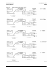
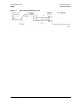
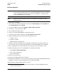
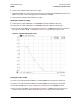
Figure 2-9 Typical Test IF Response Trace
For Option 00x and 40x Models Only: Checking the J12 Test 2 IF Out
1. Connect a test cable between the PNA Port 1 and the 85309B rear panel port Test 2 LO/IF (J11).
2. Connect a test cable between the PNA Port 2 and the 85309B rear panel port Test 2 IF Out (J12).
3. Place a marker on the PNA trace. In the frequency range of 10 – 20 MHz, the Test IF response trace
should be in the range of +21 dB to +25 dB. See Figure 2-9 for a typical Test IF response trace.
For Option 002 and 402 Models Only: Checking the J14 Test 3 IF Out
1. Connect a test cable between the PNA Port 1 and the 85309B rear panel port Test 3 LO/IF (J13).
2. Connect a test cable between the PNA Port 2 and the 85309B rear panel port Test 3 IF Out (J14).
3. Place a marker on the PNA trace. In the frequency range of 10 – 20 MHz, the Test IF response trace
should be in the range of +21 dB to +25 dB. See Figure 2-9 for a typical Test IF response trace.
IF the Operator’s Check Fails
1. Clean the cables and adapters and repeat the Operator’s Check.
2. If the Operator’s Check still fails, possibly the amplifiers are biased incorrectly or there is a faulty
component. See “Contacting Keysight” on page 1-12.