
Technical data

Service Guide 85309-90082 2-19
LO/IF Distribution Unit Operating Information
85309B Performing the Operator’s Check
6. Connect a thru adapter between the two test cables.
7. Normalize the PNA trace. If necessary, get instructions by searching the embedded Help System of the
PNA for “normalize.” After normalizing, the trace should be flat at 0 dBm
8. Remove the thru adapter between the two test cables.
Checking the J10 Reference IF Out
9. Connect the test cable on PNA Port 1 to the 85309B rear panel port Reference IF In (J4).
10. Connect the test cable on PNA Port 2 to the 85309B rear panel port Reference IF Out (J10).
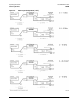
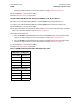
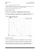
11. Place a marker on the PNA trace. In the frequency range of 10 – 20 MHz, the IF Gain trace should be in
the range of +21 dB to +25 dB, +/–0.5 dB. See Figure 2-8 for a typical IF Gain response trace.
Figure 2-8 Typical IF Gain Response Trace
Checking the J9 Test 1 IF Out
12. Connect a test cable between the PNA Port 1 and the 85309B rear panel port Test 1 LO/IF (J3).
13. Connect a test cable between the PNA Port 2 and the 85309B rear panel port Test 1 IF Out (J9).
14. Verify that the W59 jumper is in place between the J7 and J8 ports on the 85309B rear panel.
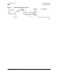
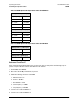
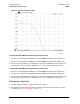
15. Place a marker on the PNA trace. In the frequency range of 10 – 20 MHz, the Test IF response trace
should be in the range of +21 dB to +25 dB. See Figure 2-9 for a typical Test IF response trace.