
Technical data

2-18 Service Guide 85309-90082
Operating Information LO/IF Distribution Unit
Performing the Operator’s Check 85309B
Reference IF and Test IF
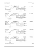
After completing the LO Power Output test, use the same cable set and perform the following steps to
perform a 2-port calibration and check the Reference IF channels.
1. On the PNA, select Preset.
2. Disconnect the 30 dB pad attenuator, if present.
3. Make the following selections on the PNA:
a. Measurement = S
21
b. Power = –35 dBm
c. IF bandwidth = 1 kHz
d. Start frequency = 10 MHz
e. Stop frequency = 100 MHz
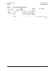
4. Connect a test cable to PNA Port 1.
5. Connect a test cable to PNA Port 2.
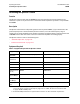
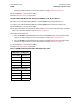
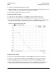
Table 2-4 85309B Options 40x Output Power Limits for HIGH Band
LO Output Power (+6 dBm Input)
Frequency Range Power Level
0.3 – 0.5 GHz > +21.3 dBm
0.5 – 3 GHz > +22.4 dBm
3 – 6.2 GHz > +24.4 dBm
6.2 – 18 GHz > +22 dBm
LO Output Power (0 dBm Input)
0.3 – 0.5 GHz > +21.3 dBm
0.5 – 3 GHz > +22.4 dBm
3 – 6.2 GHz > +24.4 dBm
6.2 – 18 GHz > +22 dBm
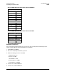
Table 2-5 85309B Options 40x Output Power Limits for LOW Band
LO Output Power (+6 dBm Input)
Frequency Range Power Level
0.1 – 1 GHz > +14 dBm
LO Output Power (0 dBm Input)
0.1 – 1 GHz > +13 dBm