
Technical data

Service Guide 85309-90082 2-17
LO/IF Distribution Unit Operating Information
85309B Performing the Operator’s Check
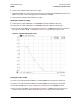
power traces with the limits across the entire frequency range in Table 2-5 on page 2-18.
34. Set the PNA Port 1 source power to 6 dBm.
35. Repeat Step 32 or Step 33, as appropriate.
For Option 002 and 402 Models Only: Checking the 85309B Test 3 LO/IF (J13) Channel
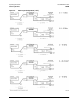
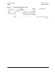
36. Connect a test cable between the PNA Port 1 and the 85309B rear panel port LO Input (J1).
37. Connect a test cable between the PNA Port 2 and the 85309B rear panel port Test 3 LO/IF (J13).
38. Set the PNA Port 1 source power to 0 dBm.
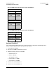
39. For Option 002 models only: Compare the output power traces from the Test 3 LO/IF (J13) port with the
limits across the entire frequency range in Table 2-3 on page 2-17.
40. For Option 402 models only:
a. Place the 85309B front panel Band Selection switch in the HIGH position, and compare the output
power traces with the limits across the entire frequency range in Table 2-4 on page 2-18.
b. Place the 85309B front panel Band Selection switch in the LOW position, and compare the output
power traces with the limits across the entire frequency range in Table 2-5 on page 2-18.
41. Set the PNA Port 1 source power to 6 dBm.
42. Repeat Step 39 or Step 40, as appropriate.
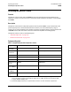
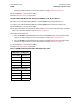
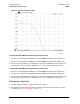
Table 2-3 85309B Standard or Options 001 or 002 Output Power Limits
LO Output Power (+6 dBm Input)
Frequency Range Power Level
0.3 – 0.5 GHz > +21.6 dBm
0.5 – 3 GHz > +24.1 dBm
3 – 6.2 GHz > +26.3 dBm
6.2 – 18 GHz > +23.5 dBm
LO Output Power (0 dBm Input)
0.3 – 0.5 GHz > +21.6 dBm
0.5 – 3 GHz > +23 dBm
3 – 6.2 GHz > +25 dBm
6.2 – 18 GHz > +23 dBm