User’s and Service Guide Agilent Technologies 85032B/E 50Ω Type-N Calibration Kits Agilent Part Number: 85032-90020 Printed in USA Print Date: July 2002 Supersedes: June 2000 © Copyright 1993, 2000, 2002 Agilent Technologies, Inc. All rights reserved.
Documentation Warranty THE MATERIAL CONTAINED IN THIS DOCUMENT IS PROVIDED "AS IS," AND IS SUBJECT TO BEING CHANGED, WITHOUT NOTICE, IN FUTURE EDITIONS. FURTHER, TO THE MAXIMUM EXTENT PERMITTED BY APPLICABLE LAW, AGILENT DISCLAIMS ALL WARRANTIES, EITHER EXPRESS OR IMPLIED WITH REGARD TO THIS MANUAL AND ANY INFORMATION CONTAINED HEREIN, INCLUDING BUT NOT LIMITED TO THE IMPLIED WARRANTIES OF MERCHANTABILITY AND FITNESS FOR A PARTICULAR PURPOSE.
Contents 1. General Information Calibration Kit Overview . . . . . . . . . . . . . . . . . . . . . . . . . . . . . . . . . . . . . . . . . . . . . . . . . . . . . .1-2 Kit Contents . . . . . . . . . . . . . . . . . . . . . . . . . . . . . . . . . . . . . . . . . . . . . . . . . . . . . . . . . . . . . .1-2 Broadband Loads. . . . . . . . . . . . . . . . . . . . . . . . . . . . . . . . . . . . . . . . . . . . . . . . . . . . . . . . .1-2 Opens and Shorts . . . . . . . . . . . . . . . . . . . . . . . . . . .
Contents 4. Performance Verification Introduction . . . . . . . . . . . . . . . . . . . . . . . . . . . . . . . . . . . . . . . . . . . . . . . . . . . . . . . . . . . . . . . . 4-2 How Agilent Verifies the Devices in This Kit . . . . . . . . . . . . . . . . . . . . . . . . . . . . . . . . . . . . 4-2 Recertification . . . . . . . . . . . . . . . . . . . . . . . . . . . . . . . . . . . . . . . . . . . . . . . . . . . . . . . . . . . . . . 4-3 Limited Recertification (Option 003). . . . . . . . . . . . . .
1 General Information 85032B/E 1- 1
General Information Calibration Kit Overview Calibration Kit Overview The Agilent 85032B and 85032E type-N calibration kits are used to calibrate Agilent network analyzers up to 6 GHz for measurements of components with 50Ω type-N connectors.
General Information Calibration Kit Overview Adapters Like the other devices in the kit, the adapters are built to very tight tolerances to provide good broadband performance. The adapters utilize a dual-beaded connector structure to ensure stable, repeatable connections. The beads are designed to minimize return loss and are separated far enough so that interaction between the beads is minimized.
General Information Incoming Inspection Incoming Inspection Verify that the shipment is complete by referring to Figure 6-1 or Figure 6-2. Check for damage. The foam-lined storage case provides protection during shipping. If the case or any device appears damaged, or if the shipment is incomplete, contact Agilent. See Table 5-1 on page 5-3. Agilent will arrange for repair or replacement of incomplete or damaged shipments without waiting for a settlement from the transportation company.
General Information Recording the Device Serial Numbers Recording the Device Serial Numbers In addition to the kit serial number, the devices in this kit are individually serialized (serial numbers are labeled onto the body of each device). Record these serial numbers in Table 1-1 for the 85032B and Table 1-2 for the 85032E. Recording the serial numbers will prevent confusing the devices in this kit with similar devices in other kits.
General Information Clarifying the Sex of a Connector Clarifying the Sex of a Connector In this manual, the sex of calibration devices and adapters are referred to in terms of their connector interface. For example, a male open has a male connector. However, during a measurement calibration, the network analyzer softkey menus label a type-N calibration device with reference to the sex of the analyzer’s test port connector—not the calibration device connector.
2 Specifications 85032B/E 2-1
Specifications Environmental Requirements Environmental Requirements Table 2-1 Environmental Requirements Parameter Limits Operating temperaturea +15 °C to +35 °C (+59 °F to +95 °F) Error-corrected temperature rangeb ±1 °C of measurement calibration temperature Storage temperature −40 °C to +75 °C (−40 °F to +167 °F) Altitude Operation < 4,500 meters (≈15,000 feet) Storage < 15,000 meters (≈50,000 feet) Relative humidity Always non-condensing Operation 0 to 80% (26 °C maximum dry bulb) St
Specifications Mechanical Characteristics Mechanical Characteristics Mechanical characteristics such as center conductor protrusion and pin depth are not performance specifications. They are, however, important supplemental characteristics related to electrical performance. Agilent Technologies verifies the mechanical characteristics of the devices in this kit with special gaging processes and electrical testing.
Specifications Mechanical Characteristics NOTE The gages for measuring type-N connectors compensate for the designed offset of 5.26 mm (0.207 inch), therefore, protrusion and recession readings are in relation to a zero reference plane (as if the inner and outer conductor planes were intended to be flush). Gage readings can be directly compared with the observed values listed in Table 2-2.
Specifications Electrical Specifications Electrical Specifications The electrical specifications in Table 2-3 apply to the devices in your calibration kit when connected with an Agilent precision interface. Table 2-3 Electrical Specifications for 50Ω Type-N Devices Device Specification Frequency (GHz) Loads Return loss ≥ 49 dB (ρ ≤ 0.00355) DC to ≤ 2 Return loss ≥ 46 dB (ρ ≤ 0.00501) > 2 to ≤ 3 Return loss ≥ 40 dB (ρ ≤ 0.01000) > 3 to ≤ 6 Female opena ±0.501 ° ±0.
Specifications Electrical Specifications 2-6 85032B/E
3 Use, Maintenance, and Care of the Devices 85032B/E 3-1
Use, Maintenance, and Care of the Devices Electrostatic Discharge Electrostatic Discharge Protection against ESD (electrostatic discharge) is essential while connecting, inspecting, or cleaning connectors attached to a static-sensitive circuit (such as those found in test sets). Static electricity can build up on your body and can easily damage sensitive internal circuit elements when discharged. Static discharges too small to be felt can cause permanent damage.
Use, Maintenance, and Care of the Devices Visual Inspection Visual Inspection Visual inspection and, if necessary, cleaning should be done every time a connection is made. Metal particles from the connector threads may fall into the connector when it is disconnected. One connection made with a dirty or damaged connector can damage both connectors beyond repair. In some cases, magnification is necessary to see damage on a connector; a magnifying device with a magnification of ≥10× is recommended.
Use, Maintenance, and Care of the Devices Cleaning Connectors Inspect Female Connectors Pay special attention to the contact fingers in the female center conductor. These can be bent or broken, and damage to them is not always easy to see. A connector with damaged contact fingers will negatively affect electrical performance and must be replaced. NOTE Inspection is particularly important when mating nonprecision to precision devices.
Use, Maintenance, and Care of the Devices Cleaning Connectors Use a lint-free swab or cleaning cloth moistened with isopropyl alcohol to remove any dirt or stubborn contaminants on a connector that cannot be removed with compressed air or nitrogen. Refer to Table 6-3 on page 6-5 for part numbers for isopropyl alcohol and cleaning swabs. a. Apply a small amount of isopropyl alcohol to a lint-free cleaning swab. b. Clean the connector threads. c.
Use, Maintenance, and Care of the Devices Gaging Connectors Gaging Connectors The gages available from Agilent Technologies are intended for preventive maintenance and troubleshooting purposes only. (See Table 6-3 on page 6-5 for part number information.) They are effective in detecting excessive center conductor protrusion or recession, and conductor damage on DUTs, test accessories, and the calibration kit devices. Do not use the gages for precise pin depth measurements.
Use, Maintenance, and Care of the Devices Gaging Connectors When to Gage Connectors Gage a connector at the following times: • Prior to using a device for the first time: record the pin depth measurement so that it can be compared with future readings. (It will serve as a good troubleshooting tool when you suspect damage may have occurred to the device.
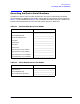
Use, Maintenance, and Care of the Devices Gaging Connectors Gaging Procedures Gaging Male Type-N Connectors NOTE Always hold a connector gage by the gage barrel, below the dial indicator. This gives the best stability, and improves measurement accuracy. 1. Select the proper gage for your connector. (Refer to Table 6-3 for gage part numbers). 2. Inspect and clean the gage, gage master, and device to be gaged. Refer to “Visual Inspection” and “Cleaning Connectors” earlier in this chapter. 3.
Use, Maintenance, and Care of the Devices Gaging Connectors Figure 3-3 85032B/E Gaging Male Type-N Connectors 3-9
Use, Maintenance, and Care of the Devices Gaging Connectors Gaging Female Type-N Connectors NOTE Always hold a connector gage by the gage barrel, below the dial indicator. This gives the best stability, and improves measurement accuracy. 1. Select the proper gage for your connector. (Refer to Table 6-3 for gage part numbers). 2. Inspect and clean the gage, gage master, and device to be gaged. Refer to “Visual Inspection” and “Cleaning Connectors” earlier in this chapter. 3.
Use, Maintenance, and Care of the Devices Gaging Connectors Figure 3-4 85032B/E Gaging Female Type-N Connectors 3-11
Use, Maintenance, and Care of the Devices Connections Connections Good connections require a skilled operator. The most common cause of measurement error is bad connections. The following procedures illustrate how to make good connections. How to Make a Connection Preliminary Connection 1. Ground yourself and all devices. Wear a grounded wrist strap and work on a grounded, conductive table mat. Refer to “Electrostatic Discharge” on page 3-2 for ESD precautions. 2. Visually inspect the connectors.
Use, Maintenance, and Care of the Devices Connections Using a torque wrench guarantees that the connection is not too tight, preventing possible connector damage. It also guarantees that all connections are equally tight each time. 2. Prevent the rotation of anything other than the connector nut that you are tightening. It may be possible to do this by hand if one of the connectors is fixed (as on a test port).
Use, Maintenance, and Care of the Devices Connections 5. Apply downward force perpendicular to the wrench handle. See Figure 3-6. This applies torque to the connection through the wrench. Do not hold the wrench so tightly that you push the handle straight down along its length rather than pivoting it, otherwise you apply an unknown amount of torque. 6. Tighten the connection just to the torque wrench break point. The wrench handle gives way at its internal pivot point. See Figure 3-6.
Use, Maintenance, and Care of the Devices Handling and Storage How to Separate a Connection To avoid lateral (bending) force on the connector mating plane surfaces, always support the devices and connections. CAUTION Turn the connector nut, not the device body. Major damage to the center conductor can occur if the device body is twisted. 1. Use an open-end wrench to prevent the device body from turning. 2. Use another open-end wrench to loosen the connector nut. 3.
Use, Maintenance, and Care of the Devices Handling and Storage 3-16 85032B/E
4 Performance Verification 85032B/E 4-1
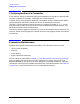
Performance Verification Introduction Introduction The performance of your calibration kit can only be verified by returning the kit to Agilent Technologies for recertification. The equipment required to verify the specifications of the devices in the kit has been specially manufactured and is not commercially available. How Agilent Verifies the Devices in This Kit Agilent verifies the specifications of these devices as follows: 1.
Performance Verification Recertification Recertification The following will be provided with a recertified kit: • a new calibration sticker affixed to the case • a certificate of calibration • a calibration report for each device in the kit listing measured values, specifications, and uncertainties NOTE A list of NIST traceable numbers may be purchased upon request to be included in the calibration report. Agilent Technologies offers a Standard calibration for the recertification of this kit.
Performance Verification Recertification 4-4 85032B/E
5 Troubleshooting 85032B/E 5-1
Troubleshooting Troubleshooting Process Troubleshooting Process If you suspect a bad calibration, or if your network analyzer does not pass performance verification, follow the steps in Figure 5-1.
Troubleshooting Returning a Kit or Device to Agilent Returning a Kit or Device to Agilent If your kit or device requires service, contact the Agilent Technologies office nearest you for information on where to send it. See Table 5-1.
Troubleshooting Returning a Kit or Device to Agilent 5-4 85032B/E
6 Replaceable Parts 85032B/E 6-1
Replaceable Parts Introduction Introduction Table 6-1 lists the replacement part numbers for items included in the 85032B calibration kit and Figure 6-1 illustrates each of these items. Table 6-2 lists the replacement part numbers for items included in the 85032E calibration kit and Figure 6-2 illustrates each of these items. Table 6-3 lists the replacement part numbers for items recommended or required for successful operation but not included in the calibration kit.
Replaceable Parts Introduction Figure 6-1 85032B/E Replaceable Parts for the 85032B Calibration Kit 6-3
Replaceable Parts Introduction Table 6-2 Replaceable Parts for the 85032E Calibration Kit Item No.
Replaceable Parts Introduction Table 6-3 Replaceable Parts—Items Not Included in the Calibration Kit Item No.
Replaceable Parts Introduction 6-6 85032B/E
A Standard Definitions 85032B/E A-1
Standard Definitions Standard Class Assignments Standard Class Assignments Class assignment organizes calibration standards into a format compatible with the error models used in the measurement calibration. A class or group of classes corresponds to the systematic errors to be removed from the measured network analyzer response. Table A-1 lists the classes of the devices in this calibration kit.
Standard Definitions Standard Class Assignments Blank Form The standard class assignments listed in Table A-1 may be changed to meet your specific requirements. Table A-2 is provided to record the modified standard class assignments.
Standard Definitions Nominal Standard Definitions Nominal Standard Definitions Standard definitions provide the constants needed to mathematically model the electrical characteristics (delay, attenuation, and impedance) of each calibration standard. The nominal values of these constants are theoretically derived from the physical dimensions and material of each calibration standard, or from actual measured response. These values are used to determine the measurement uncertainties of the network analyzer.
Standard Definitions Nominal Standard Definitions Standard Definitions System Z 0a = 50 Ω 0.093 49.992 700Μ 0 999 Coax Short (m) −36.955 26.258 5.5136 0 50 700Μ 0 999 Coax Open (m) Fixed 0 50 700Μ 0 999 Coax Broadband 0 50 700Μ 0 999 Coax Thru 17.817 50.209 2.1002G 0 999 Coax Short (f) 17.411 0 999 Coax Open (f) Freq (GHz) Standard Labeld Coax or Waveguide Delay/ Thru Max 4 Min Load Loss (Ω/s) 3 119.
Standard Definitions Nominal Standard Definitions Blank Form The standard definitions listed in Table A-3 may be changed to meet your specific requirements. Table A-4 is provided to record the modified standard definitions.
Index A adapters, 1-3 part numbers, 6-5 Agilent Technologies, contacting, 5-3 alcohol isopropyl as cleaning solvent, 3-4 altitude, 2-2 B blank form standard class assignments, A-3 standard definitions, A-6 broadband loads, 1-2 C cal kit contents, 1-2 overview, 1-2 return to Agilent, 5-3 serial number, 1-5 calibration bad, 5-2 certificate of, 1-3, 4-2 constants, 1-3 permanently stored, 1-3 limited, 1-3, 4-3 standards, 2-5 temperature, 2-2 calibration constants entering, 1-3 permanently stored, 1-3 calibrati
Index connecting, 3-14 disconnecting , 3-14 frequency specifications, 2-5 frequency range, 2-5 , 4-3 G gage connector dial, 3-7 handling, 3-8, 3-10 master, 3-8, 3-10, 6-5 reading, 3-7 zeroing, 3-8, 3-10 gage master part numbers, 6-5 using, 3-8, 3-10 gages, 1-3 gaging female connectors, 3-10 male connectors, 3-8 procedures, 3-8 gaging connectors, 3-6 when to do, 3-7 H handling, 3-15 humidity , 2-2 I impedance system, A-4 incoming inspection, 1-4 inspection damage, 3-3 defects, 3-3 female connectors, 3-4 inc
Index temperature, 2-2 supplemental characteristics, 2-3 supplemental electrical characteristics , 2-5 supplies cleaning, 1-3 system impedance setting, A-4 T tag service, 1-4, 4-3, 5-3 temperature calibration, 2-2 device, 2-2 error-corrected temperature range, 2-2 measurement, 2-2 operating range, 2-2 verification and measurement, 2-2 test data, 4-2 threads connector, 3-4 torque wrench, 1-3, 3-12 part number, 6-5 specifications, 3-12 traceability, 4-2 troubleshooting , 5-2 two-piece female open, 3-14 V ver