
Technical data

5-16
8510XF Service Quick Reference Guide
System Level Servicing & Troubleshooting
Power Level Check
Operator’s check (normal operating condition)
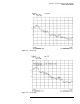
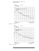
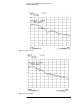
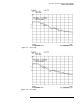
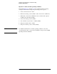
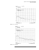
The graphs Figures 5-11 through 5-14 were obtained with the following
settings (normal default settings) after performing a factory preset:
1. Shorts connected to Ports 1 and 2
2. RF Source leveling: system (default—with conversion loss calibration)
3. BNC cable connected from millimeter-wave controller ALC output to
the RF source ALC input (default).
4. LO Source leveling: system (default)
5. Port 1 and Port 2 power level: −15 dBm (default)
6. Response reference value: −20 dB
7. Response reference position: 5 Div (default)
NOTE For additional information on normal operating conditions, refer to the
“System Operation Test” section in the “Installation” chapter of the 8510XF
Operating and Service Manual.