
Technical data

8510XF Service Quick Reference Guide
5-9
System Level Servicing & Troubleshooting
Power Level Check
6. Connect Port 1 and Port 2 together. Select {USER 2 b2} {REDEFINE
PARAMETERS} {DRIVE} {DRIVE:PORT1}
. The forward transmission signal path
power level is displayed. The power level should be approximately 2 dB
less than what was measured with a short on each test port.
NOTE The following measurements show the approximate RF signal levels
incident at the first frequency conversion stage and are given in dBm even
though the marker value is read out in dB.
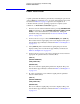
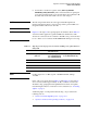
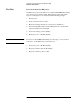
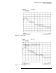
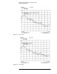
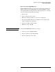
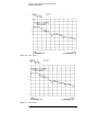
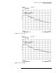
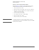
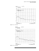
NOTE Figures 5-3 through 5-6 are typical graphs from which the data in Table 5-5
was derived. These graphs are typical 8510XF user channel traces with
offset shorts connected to Port 1 and Port 2. The RF source power level must
be set so that it does not activate the IF OVERLOAD running error message.
NOTE 0.1 dB compression, −8 dBm; typical, −10 dBm maximum; damage,
+15 dBm.
If any of the power levels shown in Table 5-5 and Figures 5-3 through 5-6
are not observed (within approximately
±5 dB), consult the “Service and
Troubleshooting” paragraphs in this Quick Reference Guide. An Agilent
Customer Engineer may be contacted for service assistance (see “Contacting
Agilent” on page v).
Additional graphs—for help with troubleshooting—are provided in the
following sections:
• “Power level check (high RF power)” on page 5-13
• “Operator’s check (normal operating condition)” on page 5-16
Table 5-5 Typical power levels for power level check (low RF power) of the mm-wave
sub-system
Raw Channel Power
Frequency Range (GHz)
0.045 to 50
Frequency Range (GHz)
50 to 85 (E7340A/E7342A)
50 to 75 (E7350A/E7352A)
Frequency Range (GHz)
75-110 (E7350A/E7352A only)
a
1 (USER 1)
−5 to −35 −30 to −50 −35 to −50
b
1 (USER 4)
−5 to −35 −30 to −50 −35 to −50
a
2 (USER 3)
−5 to −35 −30 to −50 −35 to −50
b
2 (USER 2)
−5 to −35 −30 to −50 −35 to −50