
Technical data

5-8
8510XF Service Quick Reference Guide
System Level Servicing & Troubleshooting
Power Level Check
Power Level Check
A quick operational check may be performed by measuring the power levels
of the 8510XF user parameters a
1
, b
1
, a
2
, and b
2
. Observing the appropriate
levels listed in Table 5-5 on page 5-9 gives the user a high level of
confidence that the system is operating properly. For complete system
verification, see Performance Verification, page 4-1.
1. If needed, save the current instrument state by pressing
INSTRUMENTSTATE
[SAVE]
and selecting 1-8. Press INSTRUMENT STATE [RECALL], {MORE}, {FACTORY
PRESET}
to restore the default factory instrument state. Change the
instrument settings as indicated under “Power level check (low RF
power)” on page 5-10.
2. Connect a short to test port 1. Press
PARAMETER [MENU], then {USER 1 a1}.
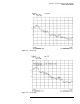
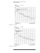
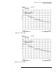
The forward reference signal path power level is displayed. The power
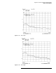
level should be approximately as indicated in Table 5-5 and Figure 5-3
on page 5-11.
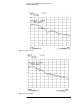
3. Select
{USER 4 b1}. The forward reflection signal path power level is
displayed. The power level should be approximately as indicated in
Table 5-5 and Figure 5-6 on page 5-12.
4. Connect a short to test port 1. In order to measure the reverse reference
signal path, the parameter must be redefined. Press:
{USER 3 a2}
{REDEFINE PARAMETERS}
{DRIVE} {DRIVE:PORT2}
{REDEFINE DONE}
The reverse reference signal path signal level is displayed. The power
level should be approximately as indicated in Table 5-5 and Figure 5-5
on page 5-12.
5. In order to measure the reverse reflection signal path, the parameter
must be redefined. Press:
{USER 2 b2}
{REDEFINE PARAMETERS}
{DRIVE} {DRIVE:PORT2}
{REDEFINE DONE}
The reverse reflection signal path power level is displayed. The power
level should be approximately as indicated in Table 5-5 and Figure 5-4
on page 5-11.