
Technical data

3-8
8510XF Service Quick Reference Guide
Making 8510XF Adjustments
To perform the conversion loss calibration:
Use the following procedure to perform the conversion loss calibration.
1. Load the BASIC, version 6.3 or greater.
2. Calibrate and zero the power sensor, and enter all cal factors versus
frequency of the 3 or 4 sensors into the text file of the conversion loss
calibration program.
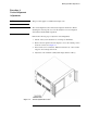
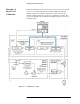
3. Connect the power sensor to the left or right test head and press
[ENTER].
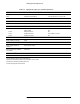
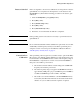
4. Create a power sensor cal factor test file. Using MS Windows Notepad,
enter the following values in the respective columns:
Save this file as
XFPWRCAL.PMC, and in the same directory as your
conversion loss cal program.
5. Load
xfpwcal.bas, and press [ENTER].
6. Press
{Run}.
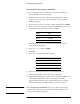
7. Select one of the following frequency ranges:
8. Select (1) for the left test-head, or (2) for the right test-head.
9. Enter the serial number of the test head up to eight digits.
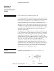
10. Approximately 20 frequencies will be used to check the 8510XF power
control. These frequencies and the corresponding levels will be
displayed if all is okay. If not, the display will have an error message
which indicates that the 8510XF leveling loop must be corrected.
NOTE Refer to Performance Verification, page 4-1, for details on the types of
computers and software needed to run the Performance Verification and
conversion loss calibration programs.
Column Entry
First Frequency (GHz)
Second Cal Factor
Third Sensor #3
Selection Frequency Range
1 0.045 to 110 GHz
2 2 to 110 GHz
3 0.045 to 85 GHz
4 2 to 85 GHz