Agilent Technologies 8510XF Network Analyzer System Service Quick Reference Guide Agilent Part Number: E7340-90013 Printed in USA Print Date: May 2002 Supersedes: June 2001
Notice Restricted Rights Legend If software is for use in the performance of a U.S. Government prime contract or subcontract, Software is delivered and licensed as "Commercial computer sofware" as defined in DFAR 252.227-7014 (June 1995), or as a "commercial item" as defined in FAR 2.101(a) or as "Restricted computer software" as defined in FAR 52.227-19 (June 1987) or any equivalent agency regulation or contract clause.
What You’ll Find in This Manual… Chapter 1 Installation “Preflight” Checkout Chapter 2 Upgrading a Source for 8510XF Chapter 3 Making 8510XF Adjustments • • • • Vertical Alignment Adjustment Degaussing the Display 8360 Series Sources Full User CAL Power Level Calibration ❍ Detector Gain Cal ❍ Conversion Loss Cal Chapter 4 Performance Verification Chapter 5 System Level Servicing and Troubleshooting • • Theory of Operation Troubleshooting Block Diagrams 8510XF Service Quick Reference Guide iii
Warranty Certification Agilent Technologies certifies that this product met its published specifications at the time of shipment from the factory. Agilent Technologies further certifies that its calibration measurements are traceable to the United States National Institute of Standards and Technology (NIST, formerly NBS), to the extent allowed by the Institute’s calibration facility, and to the calibration facilities of other International Standards Organization members.
Contacting Agilent Online assistance: www.agilent.
Safety and Regulatory Information Review this product and related documentation to familiarize yourself with safety markings and instructions before you operate the instrument. This product has been designed and tested in accordance with international standards. WARNING The WARNING notice denotes a hazard. It calls attention to a procedure, practice, or the like, that, if not correctly performed or adhered to, could result in personal injury.
1SM1-A This text indicates that the instrument is an Industrial Scientific and Medical Group 1 Class A product (CISPER 11, Clause 4). This ISM device complies with Canadian ICES-001. Cet appareil ISM est conforme a la norme NMB du Canada. This symbol indicates that the power line switch is ON. This symbol indicates that the power line switch is OFF or in STANDBY position. Safety Earth Ground This is a Safety Class I product (provided with a protective earthing terminal).
Typeface Conventions Typeface Conventions • Used to emphasize important information: Use this software only with the xxxxxX system. • Used for the title of a publication: Refer to the xxxxxX System-Level User’s Guide. • Used to indicate a variable: Type LOAD BIN filename. Instrument Display • Used to show on-screen prompts and messages that you will see on the display of an instrument: The xxxxxX will display the message CAL1 SAVED.
Contents Notice . . . . . . . . . . . . . . . . . . . . . . . . . . . . . . . . . . . . . . . . . . . . . . . . . . . . . ii What You’ll Find in This Manual… . . . . . . . . . . . . . . . . . . . . . . . . . . . . . iii Warranty . . . . . . . . . . . . . . . . . . . . . . . . . . . . . . . . . . . . . . . . . . . . . . . . . . . iv Certification . . . . . . . . . . . . . . . . . . . . . . . . . . . . . . . . . . . . . . . . . . . . . iv DOCUMENTATION WARRANTY . . . . . . . . . . . . . . . . . . . . . . . .
High Band Verification (> 50 GHz) . . . . . . . . . . . . . . . . . . . . . . . . CW Frequency Accuracy Test . . . . . . . . . . . . . . . . . . . . . . . . . . . . . . . Materials Required . . . . . . . . . . . . . . . . . . . . . . . . . . . . . . . . . . . . . Procedure . . . . . . . . . . . . . . . . . . . . . . . . . . . . . . . . . . . . . . . . . . . . . Performance Test Record . . . . . . . . . . . . . . . . . . . . . . . . . . . . . . . . 5.
1 Installation “Preflight” Checkout System Overview The 8510XF network analyzer system has been designed to measure broadband devices to 110 GHz, on-wafer or coax, fully calibrated, in a single frequency sweep. Single RF connection to 110 GHz The 8510XF system provides frequency coverage from 45 MHz to 110 GHz in a single sweep with a single connection. Millimeter-wave measurements in 1.0 mm coax With a single connection, fully error-corrected measurements to 110 GHz are made in 1.0 mm coax.
Installation “Preflight” Checkout System Diagrams System Diagrams Rack Diagram Configured for Coaxial Measurements Figure 1-1 Rack diagram configured for coaxial measurements 1-2 8510XF Service Quick Reference Guide
Installation “Preflight” Checkout System Diagrams Rack Diagram Configured for Wafer-Probe Measurements Figure 1-2 Rack diagram configured for wafer-probe measurements 8510XF Service Quick Reference Guide 1-3
Installation “Preflight” Checkout System Diagrams Front View Cabling Diagram Figure 1-3 Front view wiring diagram 2.4 mm 3.5 mm SMA testhead.
Rear View Cabling (rack mounted source) Figure 1-5 Installation “Preflight” Checkout System Diagrams Rear view wiring diagram (rack mounted source) 8510XF Service Quick Reference Guide 1-5
Installation “Preflight” Checkout System Diagrams Rear View Cabling (table mounted source) Figure 1-6 Rear view wiring diagram (table mounted source) 1-6 8510XF Service Quick Reference Guide
Installation “Preflight” Checkout 8510XF Option 006 8510XF Option 006 8510XF Option 006 provides the capability to add an additional 8510 series test set provided Option 001 is installed in the test set. Option 006 includes: • • Figure 1-7 Coupler and amplifier added to millimeter-wave controller 2.4 mm termination added to rear panel 8510XF Option 006 The configuration for the 8510XF Option 006 is as shown in Figure 1-8.
Installation “Preflight” Checkout 8510XF Option 006 1-8 8510XF Service Quick Reference Guide
2 Upgrading a Source for 8510XF All 8360 series sources are compatible, but only the 83621A/B or 83651A/B are recommended in order to insure full functionality of the 8510XF. Table 2-1 shows the upgrade options required. NOTE 83651/21A and 83650/20A/B will also work for upgraded 8510XF systems as long as it has test port flatness correction modification or capability, rear panel output (Option 004), and 1 Hz frequency resolution (Option 008) installed.
Upgrading a Source for 8510XF 2-2 8510XF Service Quick Reference Guide
3 Making 8510XF Adjustments NOTE This chapter covers both the CRT and LCD displays. Some display-related adjustments apply only to instruments with CRT display. The following table provides adjustments most frequently needed for 8510XF system service. Most of the 8510XF is self-adjusting except for the following: Table 3-1 Frequently used 8510XF adjustments Procedure1 Title Adjustment Function Assembly Adjusted 1 Vertical Alignment Adjustment2 Aligns softkey labels and mechanical softkey buttons.
Making 8510XF Adjustments Table 3-2 Equipment required for 8510XF adjustments Equipment Recommended Model Substitute CRT demagnetizer or bulk tape eraser1 Radio Shack Model 44-233 Techno Tool (USA) or Nietronix (Europe) 692PR022 1 to 2 amp pencil sharpening motor (base held near CRT with motor on), or electric drill Flat-head screwdriver (small) At least 2 inches long, non-conductive none 10 dB pad 8493C 8360 series source with built-in attenuator 85102A/B and test set adjust software Part N
Making 8510XF Adjustments Procedure 1. Vertical Alignment Adjustment NOTE This procedure applies to a CRT based display only. NOTE The vertical alignment can be affected by magnetic interference. Before adjusting the vertical position, be sure the analyzer is in a non-magnetic environment and the CRT is degaussed. Perform the following steps to adjust the vertical alignment. 1. Switch on the system and allow it to warm up for 60 minutes. 2.
Making 8510XF Adjustments Procedure 2. DeGaussing (Demagnetizing) the Display NOTE This procedure applies to a CRT based display only. Use any CRT demagnetizer or bulk tape eraser for this procedure. The color monitor display is very susceptible to external magnetic fields, such as metal frame tables, welded cabinets, the earth, unshielded motors, and other sources. The usual symptom is discoloration or slight dimming of the display (usually near a top corner of the CRT).
Making 8510XF Adjustments Procedure 3. 8360 Series Sources Full User CAL Full User CAL initiates a full synthesizer calibration. The calibration performed is instrument state dependent. For example, if the synthesizer is in ramp sweep mode, a sweep span and an auto track calibration are performed. If the synthesizer has amplitude modulation active on an SW signal, then RF peaking and AM bandwidth calibrations are performed. For 8510XF purposes, only ramp-sweep mode is needed.
Making 8510XF Adjustments Procedure 4. Power Level Calibration Power level calibration insures leveled power at ports 1 and 2. To level the power, we sense the IF signal which correlates to RF level. Since the translation function is frequency dependent, we need to measure the translation function using the conversion loss calibration procedure. The power level calibration is accomplished using IF leveling as shown in the following circuit.
Making 8510XF Adjustments Detector Gain Cal Before we begin the conversion loss calibration, we must perform a detector gain calibration to compensate for the imprecision of the detector board (E7340-60015 A7). Perform the following procedure for the detector gain calibration: 1. Under the Auxiliary Menus, press [System] hard key. 2. Press {More} softkey. 3. Press {RF Power Config} softkey. 4. Press {More} softkey. 5. Press {Reset Det Gain Cal} softkey. 6.
Making 8510XF Adjustments To perform the conversion loss calibration: Use the following procedure to perform the conversion loss calibration. 1. Load the BASIC, version 6.3 or greater. 2. Calibrate and zero the power sensor, and enter all cal factors versus frequency of the 3 or 4 sensors into the text file of the conversion loss calibration program. 3. Connect the power sensor to the left or right test head and press [ENTER]. 4. Create a power sensor cal factor test file.
4 Performance Verification Verification Overview NOTE The verification procedures in this chapter work for all 8510 and 8510XF hardware configurations by substituting the proper 8510 source, test set, accessories, and millimeter wave controller. Performance verification software Rev. A.05.00 or greater will be available only in DOS format, and will work with laptops or PCs that have the required accessories installed. Refer to “Materials Required” on page 4-2.
Performance Verification Materials Required Calibration and Frequency Ranges The following materials are required to run the tests: • • • 8510XF system with accessories • Laptop or PC running BASIC for Windows (3.1/95/NT) (Rev. 6.3 or greater) • • • GPIB Card for PCs (National Instruments or HP) 85059A 1.0 mm Precision Calibration and Verification Kit PC-based, 8510 Specification and Performance Verification Software (Rev. A.05.
Performance Verification Frequency ranges For most of the menu items in the software, there are two or more selections that pertain to the 8510XF. These menu selections are differentiated by: A. The frequency range of the millimeter wave subsystem ❍ ❍ ❍ E7352A: 110 GHz subsystem E7342A: 85 GHz subsystem Option 005: 45 MHz to 2 GHz B. The portion of the subsystem’s frequency range that is being verified (the ranges above and below 50 GHz are verified separately).
Performance Verification Verification Setup Verification Setup General Preparation Prepare for performance verification by completing the following steps: 1. Measure the environment temperature and humidity. The temperature must be between +20 °C and +26 °C. Additionally, the temperature cannot vary by more than 1°C after calibration. 2. Perform a good installation “preflight” checkout on the 8510XF system. 3. Power on the system components in the following order: a. Sources b.
Performance Verification Verification Setup NOTE Rev. A.05.00 or greater of the performance verification software is backwards compatible. So, it is acceptable to replace the older version you have on the PC. 3. Run the program by clicking on the “Spec8510” icon or selecting: Start, Programs, 8510, Spec8510. The following warning messages will be displayed: A valid Basic for Windows GPIB driver for your board (if any) has not been loaded.
Performance Verification Verification Setup 3. A screen prompt will give you the opportunity to set the date and time. Press the [Y] key on the PC to skip this step, or press [N] to set the date and time. 4. The program loads the System Configuration file, and displays the System Hardware Configuration Menu. Use this menu to specify the equipment you are using, and the frequency range you are verifying (refer to “Frequency ranges” on page 4-3).
Performance Verification Verification Setup Printer selection 1. From the Main Menu (choosing printer options): a. Select System config. b. Select Software Config. c. Select Printer Connected to: 2. Select printer output choice (refer to Table 4-5) Table 4-5 Printer table of selections Printer Connected To: GPIB WIN Printer1 LPT1 LPT2 File2 1. Windows default printer 2. Under Printer Redirection (File): Verify directory path exists before entering name of path 3.
Performance Verification Verification Procedures Verification Procedures Low Band Verification (< 50 GHz) The following steps assume the hardware configuration has been previously setup for Low Band Verification (< 50 GHz) in step 4 on page 4-6 under Software Configuration. 1. From the Main Menu select Verify System to go to the System Performance Verification Menu. 2. Select Serial Numbers to enter serial numbers of system and components. 3.
Performance Verification Verification Procedures c. To make the thru connection, gently slide the right test (port 2) towards the left test head (port 1) a little bit at a time, while turning the threaded ring on the left head test port connector by hand onto the cable attached to the right test head. Do not use the threaded ring on the test port connector to pull the cable into the connector. Repeat this process until the cable is firmly seated into port 1, then make the threaded ring barely finger tight.
Performance Verification Verification Procedures 11. Select Select Standard to return to the Standard Selection Menu. Repeat steps 5 through 10 above for the other verification standard (refer to Table 4-6 on page 4-9). 12. Select Prior Menu until the Main Menu appears. High Band Verification (> 50 GHz) NOTE Before verification of the high band frequencies it is necessary to: 1) select new hardware for the system, and 2) perform a calibration (for the frequency band > 50 GHz). 1.
Performance Verification Verification Procedures 9. Verify Cal Set for 45 MHz Measurement (If Required) is set to No. 10. Select Done and follow the program prompts. 11. Select Measure Data to measure the verification standards. Follow the program prompts. 12. When verification has been completed view the data, then print or save (if required). If needed the verification standard can be remeasured by selecting: Repeat Measure. 13. Select Select Standard to return to the Standard Selection Menu.
Performance Verification CW Frequency Accuracy Test CW Frequency Accuracy Test NOTE The CW frequency accuracy test should be performed prior to doing the conversion loss calibration adjustment or detector gain calibration. Source frequency accuracy is tested across the entire sweep range for 8360 sources. The CW frequency accuracy is measured with a frequency counter. Materials Required The following materials are required to run the tests: • • 5343 Option 001, 10 MHz to 26.
Performance Verification CW Frequency Accuracy Test 3. To set the frequency using the analyzer front panel, press STIMULUS [CENTER] [MENU] {SINGLE POINT}. Enter the start frequency of the source. 4. Measure RF and LO frequencies with the counter, and record these values on the test record at the end of this section. 5. From the analyzer front panel, enter the frequency per the tables at the end of this section. NOTE Be sure to connect RF and LO output to the 500 MHz to 26.
Performance Verification CW Frequency Accuracy Test Performance Test Record Table 4-7 Record the measured frequencies for RF source readings on Table 4-7, and for LO source on Table 4-8. Performance test record for CW frequency accuracy test (RF source) Instrument Model: _________________ Report Number: __________________________ Date: _______ Frequency Minimum Specification Recorded Results Maximum Specification Uncertainty1 45 MHz 44.999955 MHz 45.000045 MHz 10 Hz 2 MHz 1.999998 GHz 2.
s1 Two-Band Calibration Procedure for 8510XF Performance Verification Clarifying Connector Sex: The calibration standard labels that appear in the 8510XF softkey calibration menus specify connector sex as "(M)" or "(F)". The sex designator refers to the sex of the test port connector to which the calibration standard is connected (not the sex of the calibration standard connector).
5 System Level Servicing & Troubleshooting This chapter describes the basic servicing and troubleshooting techniques for the 8510XF system.
System Level Servicing & Troubleshooting Theory of Operation Theory of Operation The 8510XF applies RF test signals to the DUT, and compares these incident signals to whatever is reflected from (or transmitted through) the DUT. The incident, reflected, and transmitted signals are separated out by means of directional couplers, and mixed down to create a set of four IF inputs to the analyzer, as illustrated below.
System Level Servicing & Troubleshooting Theory of Operation At this simplified level of description, system operation does not differ from that of other 8510-based systems. What makes the 8510XF unique is the means by which it covers its extremely wide frequency range. Figure 5-2 shows how the 8510XF test set is divided into frequency bands. For the sake of simplicity, this figure only shows half of the test set.
System Level Servicing & Troubleshooting Theory of Operation Millimeter Wave Controller The controller has more functions than are illustrated in Figure 5-2 on page 5-3. It controls the switching of RF paths in the microwave subheads and test heads at different points in the system’s frequency range.
System Level Servicing & Troubleshooting Theory of Operation 0.045 to 2 GHz Band In the .045 to 2 GHz range, the signal from the RF source is not multiplied; it is applied directly to the mixers. The mixers for this range are located in the millimeter wave controller, and are designed to use the fundamental of the LO input frequency. This applies to 8510XF systems equipped with Option 005 only.
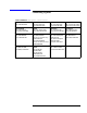
System Level Servicing & Troubleshooting 8510XF Firmware Specifications 8510XF Firmware Specifications Operating Parameters Frequency Limits: 45 MHz to 85 GHz (E7340A/E7342A with Option 005) or 45 MHz to 110 GHz (E7350A/E7352A with Option 005) Band Crossings: Table 5-1 Table 5-2 Step Mode Band crossings (45 MHz- 85 GHz) RF Frequency RF Harm LO Harm Band 45 MHz - 2 GHz 1 1 0 2 - 18 GHz 1 1 1 18 - 50 GHz 1 3 1 50 - 64.2 GHz 2 12 2 64.
System Level Servicing & Troubleshooting 8510XF Firmware Specifications Sweep Time Hardware States Similar to 8510C. The hardware states specific to the 8510XF are as shown in Table 5-3.
System Level Servicing & Troubleshooting Power Level Check Power Level Check A quick operational check may be performed by measuring the power levels of the 8510XF user parameters a1, b1, a2, and b2. Observing the appropriate levels listed in Table 5-5 on page 5-9 gives the user a high level of confidence that the system is operating properly. For complete system verification, see Performance Verification, page 4-1. 1.
System Level Servicing & Troubleshooting Power Level Check 6. Connect Port 1 and Port 2 together. Select {USER 2 b2} {REDEFINE PARAMETERS} {DRIVE} {DRIVE:PORT1}. The forward transmission signal path power level is displayed. The power level should be approximately 2 dB less than what was measured with a short on each test port.
System Level Servicing & Troubleshooting Power Level Check Test Plots Power level check (low RF power) The RF source power level must be set so that the IF OVERLOAD running error message is not activated when obtaining these graphs. The graphs Figures 5-3 through 5-6 were obtained with the following settings: 1. Factory preset 2. Shorts connected to Ports 1 and 2 3. RF Source leveling: internal (no conversion loss calibration) 4.
System Level Servicing & Troubleshooting Power Level Check Figure 5-3 User 1 (a1) Figure 5-4 User 2 (b2) 8510XF Service Quick Reference Guide 5-11
System Level Servicing & Troubleshooting Power Level Check Figure 5-5 User 3 (a2) Figure 5-6 User 4 (b1) 5-12 8510XF Service Quick Reference Guide
System Level Servicing & Troubleshooting Power Level Check Power level check (high RF power) The IF OVERLOAD running error message is normal when obtaining these graphs. A power level of +10 dBm will over drive the 8510XF so you can see the intermodulation leveling differences. The graphs Figures 5-7 through 5-10 were obtained with the following settings: 1. Factory preset 2. Shorts connected to Ports 1 and 2 3. RF Source leveling: internal (no conversion loss calibration) 4.
System Level Servicing & Troubleshooting Power Level Check Figure 5-7 User 1 (a1) Figure 5-8 User 2 (b2) 5-14 8510XF Service Quick Reference Guide
System Level Servicing & Troubleshooting Power Level Check Figure 5-9 User 3 (a2) Figure 5-10 User 4 (b1) 8510XF Service Quick Reference Guide 5-15
System Level Servicing & Troubleshooting Power Level Check Operator’s check (normal operating condition) The graphs Figures 5-11 through 5-14 were obtained with the following settings (normal default settings) after performing a factory preset: 1. Shorts connected to Ports 1 and 2 2. RF Source leveling: system (default—with conversion loss calibration) 3. BNC cable connected from millimeter-wave controller ALC output to the RF source ALC input (default). 4. LO Source leveling: system (default) 5.
System Level Servicing & Troubleshooting Power Level Check Figure 5-11 User 1 (a1) Figure 5-12 User 2 (b2) 8510XF Service Quick Reference Guide 5-17
System Level Servicing & Troubleshooting Power Level Check Figure 5-13 User 3 (a2) Figure 5-14 User 4 (b1) 5-18 8510XF Service Quick Reference Guide
No Obvious Failure Type Do a Pre-Operational Check of the 8510XF System What's Wrong? 1. Do you have any self test failures, running error messages (beeping) or raw channel power (unratioed power) problems? = MAGIC QUESTION. Check Front and Rear Panel control settings, cables and GPIB addresses. Check the 85101 free run switch on the A5 Processor Board (all zeros), and proper firmware revisions for source and 8510XF (you may need to reload the Operating System in an extreme case).
85101 is OK Main Service Functions Menu NOTE: From this point, the problem is probably one of the remaining instruments; the 85102, sources, test heads, the mm-wave controller or their interfaces. From Sheet 1 You can use the 8510XF, power-up self tests, running error messages, a1, a2, b1, and b2 raw channel displays, troubleshooting LED's, and passed installation data and displays to help pinpoint the problem to an instrument.
HOW TO READ THIS BLOCK DIAGRAM: Self Test Indicators for Millimeter Wave Controller GPIB Board THIS DIAGRAM SHOWS A TYPICAL 851OXF SYSTEM CONFIGURATION. NOTE THAT THE CIRCUIT BOARDS AND ASSEMBLIES HAVE NUMBERS PRECEDED BY THE LETTER 'A', THAT NUMBER IDENTIFIES THE ASSEMBLY. THE OTHER NUMBERS REFER TO THE LIST ON SHEET 2. If the ACTIVE LED on the Front Panel does not light within two seconds of turn on, or lights immediately, the test has not passed it’s Self Test.
SELF TESTS 1. A5 PROCESSOR EPROM (self test and service program PROM using checksum) 2. A5 PROCESSOR RAM (test processor memory using data complement technique) 3. A7 DATA BUS TEST (test I/O data bus) 4. A4 DISPLAY PROCESSOR 5. A4 DISPLAY RAM 6. A7 TIMER/CLOCK/RS – 232 7. A7 PUBLIC GPIB (Read/Write test of GPIB register) 8. A7 SYSTEM BUS (Read/Write) test of system bus register) 9. INTERRUPT SYSTEM (test interrupts) 10. A5 MULTIPLIER (PERFORMS a complex multiply) 11. A7 DISC CONTROLLER 12.
SELF TESTS 1. A5 PROCESSOR EPROM (self test and service program PROM using checksum) 2. A5 PROCESSOR RAM (test processor memory using data complement technique) 3. A7 DATA BUS TEST (test I/O data bus) 4. A14 DISPLAY PROCESSOR 5. A14 DISPLAY RAM 6. A7 TIMER/CLOCK/RS – 232 7. A7 PUBLIC GPIB (Read/Write test of GPIB register) 8. A7 SYSTEM BUS (Read/Write test of system bus register) 9. INTERRUPT SYSTEM (test interrupts) 10. A5 MULTIPLIER (PERFORMS a complex multiply) 11. A7 DISC CONTROLLER 12.