
Technical data


85108L System Manual
System Service and Troubleshooting
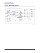
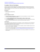
85108 IF/Detector Option 008 Pulsed-RF IF Path Troubleshooting Flowchart
6-16
Procedure 3: A2 Pulse IF MUX Test IF Path Check
Use this check only if the a1 or the a2 pulsed-RF IF signal path looks bad.
If the connections/setup correct the problem, carry out the instructions in the conclusion column. If
the problem isn’t corrected, proceed to the next step.
NOTE Always return any moved cables to their original connections before proceeding to the
next step.
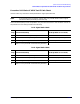
a1 IF Signal Path Check
Step Connections/Setup
Conclusion
(if the problem is corrected)
1 Move W45 cable on A14J5 to A14J6 replace IF Mixer board
2 Move W46 cable on A2J5 to A2J7.
Redefine a2 to: DRIVE: PORT1
replace W45 (A14J5 to A14J7)
3 Redefine a2 to: DRIVE: PORT2.
If a2 IF signal is okay
replace A2 pulse IF MUX board
4 Return to the pulsed-RF troubleshooting flowchart
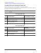
a2 IF Signal Path Check
Step Connections/Setup
Conclusion
(if the problem is corrected)
1 Move W46 cable on A13J5 to A13J6 replace A13 IF Mixer board
2 Move W45 cable on A2J7 to A2J5.
Redefine a2 to: DRIVE: PORT2
replace W46 (A13J5 to A2J5)
3 Redefine a21to: DRIVE: PORT1
If a1 IF signal is okay
replace A2 pulse IF MUX board
4 Return to the pulsed-RF troubleshooting flowchart