
Technical data


85108L System Manual
System Service and Troubleshooting
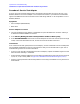
85108 IF/Detector Option 008 Pulsed-RF IF Path Troubleshooting Flowchart
6-14
Procedure 1. Service Test Adapter
If one or more user channels appear faulty, the problem could be with the source, test set, or the
85102 IF/detector. The service adapter is a source/test set emulator. It provides the same 20 MHz
signal to the 85102 as the test set and source thus indicating whether or not the problem is in the
85102 IF/detector.
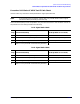
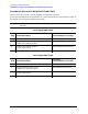
Equipment
• Service adapter (85102-60210)
•BNC cable
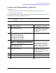
Service Adapter Procedure
1. Connect the 85102 service adapter to the 85102 rear panel 20 MHZ OUT connector and the J2
IF-DISPLAY INTERCONNECT connector.
2. Press RECALL [MORE] [FACTORY PRESET] MARKER STIMULUS MENU [STEP].
3. Press PARAMETER MENU and look at the unratioed power of each user channel (User1 through
User4). The traces should be flat lines, and all four channels should look similar.
Conclusions
If all of the channels look good (with the service adapter), and all looked bad in the unratioed power
test, the 85101 and 85102 are working. The problem is likely source related. Refer to your source
troubleshooting manual for further information.
• If all four User channels look bad (with the service adapter), suspect the 20MHz signal from the
A6 clock board assembly in the 85102.
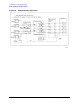
• Single channel problems suggest the IF mixer board corresponding to the User function (channel
a1, b1, a2, or b2) is faulty. Refer to Figure 6-5, “85102B IF-Detector Block Diagram (1 of 2).”.
• Multiply channel problems indicate the problem is most likely in the 85102 circuitry after the IF
Mixer boards.