
Technical data


85108L System Manual
System Service and Troubleshooting
Troubleshooting Strategy
6-8
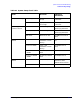
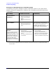
Running Error Messages Specific to Pulsed-RF Systems
The following running error messages are specific to pulsed-RF systems. If your system shows a
different running error message than is listed here, refer to the 8510C On-Site Service Manual for
an explanation.
Error Message Probable Cause of Failure Troubleshooting
PULSE CAL FAILURE ON
TEST/REFERENCE
CHANNEL(S)
1
1. This error message reports a failure detected in the pulsed-RF circuitry.
• 85102 A2 multiplexer board
• 85102 A3 and A4 test and
reference channel detector
boards
• 85102 A16 sample and hold
board
PULSE CAL FAILURE ON
BOTH CHANNELS
• 85102 A6 clock board
• 85102 A2 multiplexer board
• 85102 A16 sample and hold
board
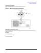
Remove W52 from A2J4 and check the
output at A2J4 with an oscilloscope. The
output should be about 0.6 peak-to-peak into
the 1 MOhm input impedance of the
oscilloscope. If the output is missing or much
lower than typical, replace the A8 Clock
board.
UNABLE TO LOCK TO EXT 10
MHZ REF
2
This error message indicates the
10 MHz external input to the
85106 A6 clock assembly is more
than +500 Hz off frequency. The
level should be > 0 dBm. If the
external input is off frequency or
is less than 0 dBm, the A6
assembly sets the LIFSRQ low,
alerting the CPU to the unlocked
condition.
2. This message is not applicable unless you are locking to an external source such as in a multiple source network
analyzer system.
• A6 clock assembly erroneously
set LIFSRQ low
• A6 clock LIFSRQ signal is pulled
low along the way to the 85101
A5 CPU
• +5 V input to the 85102 A6 clock
is intermittent
• Run the 85102 Service Program tests in
the “run all” mode.
• Check the 10 MHz input signal
frequency and amplitude that you are
applying to the rear panel of the 85102.
• Refer to your source troubleshooting
manual for the 10 MHz RF output level.