
Technical data


85108L System Manual
Adjustments
Overview
5-5
7. On the 8510, press:
PARAMETER MENU [USER 2 b2]
RESPONSE REF VALUE [MARKER]
RESPONSE SCALE
[.] [0] [2] [X1]
SYSTEM [RESET IF CORRECTION]
STIMULUS MENU [NUM PTS] [101]
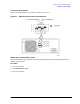
8. Adjust the two variable ceramic capacitors, located on the A3 Pulse Detector board near J2 and
J3, for minimum ripple (refer to Figure 5-2). Press
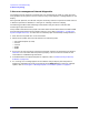
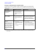
[RESET IF CORRECTION]. See Figure 5-3 and
Figure 5-4 for typical network analyzer display traces. Re-center the trace by changing the
Reference Value if necessary.
NOTE Noise can sometimes make this adjustment appear temporarily out of specification.
Ignore non-repeatable spikes.
9. Move the test cable to J5 on the A2 IF MUX board (refer to Figure 5-2) and replace the original
cable on J3. Repeat this procedure from step 6 substituting
[USER 3 a2] for [USER 2 b2]. Adjust
the capacitors on the A4 Pulse Detector board instead of the board. The ripple should be
<0.06 dB peak-to-peak after
[RESET IF CORRECTION].
10.When the A3 and A4 boards have been adjusted, turn the instrument OFF, remove the test cable
and replace the original cable on J5. Replace the top cover on the IF/detector. Reconnect the
system bus cables to the sources. Reconfigure the network analyzer with the display/processor
on top of the IF/detector.
This completes the adjustment procedure. Continue with “Operational Tests” on page 3-5.