
Technical data


85108L System Manual
Adjustments
Overview
5-4
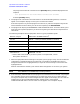
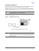
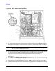
Figure 5-2 A2 IF MUX Board Connections
1. For racked systems, remove the rack mounting screws from the front of the 85102B. Slide the
instrument forward slightly to give you access to the A2, A3, and A4 boards (refer to Figure 5-2).
NOTE For benchtop configurations, the 85102 is placed on top of the 85101 display/processor
for easy access to the pulsed-RF boards.
2. Turn all the instruments off and move the top cover of the 85102B back to allow access to the A2,
A3, and A4 boards only. (Keeping the 85102 partially covered maintains the operating
temperature as close as possible to operating temperature with the cover fully on.)
3. Turn on all instruments in the adjustment setup and allow the equipment to warm up for at
least one hour.
4. On the 8510, press
DOMAIN [PULSE PROFILE]. Ignore the SYSTEM BUS ADDRESS ERROR on the
network analyzer display.
5. Set the source for a power level between −10 and −15 dBm, and a CW frequency of 20.1 MHz.
6. Use the test cable to connect the RF source output to A2J3 (disconnect the cable that is currently
to A2J3).