
Technical data


85108L System Manual
Adjustments
Overview
5-3
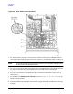
A3/A4 Detector Adjustment
The A3 and A4 pulse detector boards in the 85102 IF detector must be adjusted after installation for
minimum circularity error. Follow the procedure below to make this adjustment.
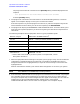
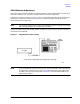
Configure your system as show in Figure 5-1. This is the standard pulsed-RF system configuration
except that a connection is made from the RF source to the A2 assembly, and the RF source is
disconnected from the system bus.
NOTE For benchtop configurations, notice that the 85102 IF detector is placed on top of the
85101 display/processor for the adjustment procedure.
Use the test cable and the SMA to SMB adapter to make the connection from the source output to
the A2 board in the 85102B.
Figure 5-1 Adjustment Procedure Setup
NOTE All of the pulsed-RF system instruments can remain connected in the system during
the adjustment procedure as long as they are powered OFF during the adjustment
procedure. Only the instruments used in Figure 5-1 should be powered ON for the
adjustment procedure.