
Technical data


85108L System Manual
Adjustments
Overview
5-2
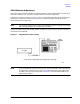
Overview
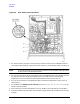
This section contains the procedures for adjusting the pulse detector boards (A3 and A4) in the
85102 IF detector. These boards must be adjusted for minimum circularity error when they are
replaced, swapped with each other, or when the 85102 IF detector is upgraded to include pulsed-RF
capability (using the 8511B upgrade kit).
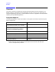
Equipment Required
The following equipment is required (in addition to the system instruments) to perform the pulse
detector adjustments.
Item Agilent Part/Model Number
RF source
(CW sinewave, 20.1 MHz, −10 to −15 dBm
3324A, 3325, 8340/41B, 8360 series
1
1. Only those that will provide 20.1 MHz.
Test cable
(required for the adjustment procedure,
included in the 85111A/B upgrade kits
85111A-60001
Adapters
2
2. Some combination of these adapters may be required to use the test cable with your
source in the adjustment procedure.
Type-N (m) to BNC (f) 1250-0780
SMA (m) to BNC (m) 1250-1787
BNC (f) to BNC (f) 1250-0080
Type-N (m) to BNC (f) 1250-0077