
Technical data


85108L System Manual
Specifications and Performance Verification
Performance Verification Procedure
4-10
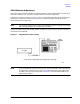
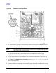
28.When you are ready to measure the verification device, press
[MEASURE DATA] and respond to
the prompts on the computer display. The program will initialize the system and give
instructions for making the proper connections. Measure all of the devices in your kit.
Press
[PRINT ALL] and the program will print a complete results sheet for the measurement of
the device. If the device fails at any frequency, the letter F will appear in the column. A pass/fail
notice will appear at the bottom of the sheet.
NOTE The uncertainty limits are wider (larger) when operating in the pulsed-RF, wide BW
mode than when operating in the nonpulsed-RF, normal BW mode. This is due to the
wider bandwidth of the IF.
29.This completes the pulsed-RF system performance verification.
General Characteristics
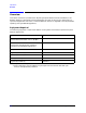
Table 4-1 lists the general characteristics of the 85108L pulsed-RF system. General characteristics
are typical, non-warranted values and are included for user information.
Table 4-1 General Characteristics
Rise Time
10% to 90% of the test and reference channel detectors: 300 nanoseconds.
Setting Time
The time required for a ratioed, high-leveled measurement to reach within
0.1 dB of its final value when the system is in pulse profile mode.
Equivalent
Measurement
Bandwidth
The effective post-detection bandwidth of the test and reference detectors in
the 8510.
Trigger Level TTL
Trigger Width The minimum pulse width to be applied to the rear panel input of the 8510
for the 8510 to make a measurement. (External trigger mode: 100
nanoseconds)
Minimum Time
Delay
The minimum time span of the x-axis of the 8510 display in pulse profile
mode: 5 nanoseconds.
Maximum Time
Delay
The maximum time span of the x-axis of the 8510 display in pulse profile
mode: 40 milliseconds.