
Technical data


85108L System Manual
Specifications and Performance Verification
Performance Verification Procedure
4-6
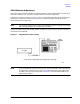
The program’s title banner information and a
[RESUME] softkey should be displayed on the
computer.
8510 Specification and Performance Verification Software
Press the
[RESUME] softkey.
5. The program will load several more files. When it has finished loading the files, a menu will
appear on the computer display to allow you to set the time and date.
Press the computer Y key and the program will continue, or press the computer N key for NO
and set the date and time. When your entries are complete, press
RETURN/ENTER.
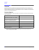
6. The program will display the HARDWARE CONFIGURATION menu. This menu allows you to
select the type of system equipment you will be using during the calibration and performance
verification.
The following example shows the equipment used in a typical pulsed-RF system:
7. Select the equipment above according to the system you are going to verify. The active selection
is denoted by a highlighted field on the CRT/LCD. Use the NEXT and PREVIOUS keys to
change the selection in the highlighted area, if required. Use the Tab key to move to the next
highlighted field.
Make all the selections necessary until the hardware configuration is correct for your system.
NOTE Select 83620B for the 83620B Option H80 synthesizer.
8. Press the softkey labeled DONE and the program will load the files from the disk. The program
will remember the last system configuration you select and, when you run it again (without
turning the computer Off), the same configuration will appear on the display. You can reset the
configuration by using the PROGRAM RESET softkey, found in the SYSTEM
CONFIGURATION menu. The main menu will now appear on the computer display.
Network analyzer
8510C 008 - Wide BW Detectors
a
a. Select “8510 Color Model” if you want to perform a nonpulsed-RF, normal
BW system verification.
Test set 85110L - 7 mm S-parameter (45 MHz to 2.0 GHz)
Source 83620B - Synthesizer (10 MHz to 2.0 GHz)
Calibration kit 85050B - 7 mm standard
Calibration technique SL - sliding load cal
Test port cable 11857D - pair of short cables (7.0 mm to 7.0 mm)
Verification kit 85051A/B - 7.0 mm